quadEM.adl
quadEM supports quad electrometers/picoammeters, typically used for photodiode-based x-ray beam position monitors, or split ion chambers. They can also be used for any low-current measurement that requires high speed digital input. There is support for several models:
The AH401 series, NSLS_EM, and APS_EM are based on the same principle of an op-amp run as a current amplifier with a large feedback capacitor, and a high resolution ADC. The AH501 series, TetrAMM, and NSLS2_EM are based on a transimpedance input stage for current sensing, combined with analog signal conditioning and filtering stages. The AH501C, AH501D, and TetrAMM have an integrated programmable bias supply.
The quadEM software includes asyn drivers that provide support for the following:
This can provide "fast feedback" via an asyn D/A converter (e.g. dac128V), also at speeds up to 20000 Hz, 6510 Hz, 1000Hz, 2500 Hz, or 813Hz. If it is run slower it does signal averaging. This support is provided in the synApps std module. The quadEM drivers do the callbacks on the asynFloat64 interface required to use the epid fast feedback device support. This fast feedback is limited to controlling devices in the same IOC as the quadEM driver, because it uses asyn links.
The epid record can also be used in "slow feedback" mode using the averaging provided by the primary averaging or fast averaging records described above. In this mode it can use Channel Access links, and so it not constrained to controlling devices in the same IOC.
The following manuals provide detailed information on these devices:
The support is based on asynNDArray driver from areaDetector, which in turn is based on asynPortDriver. It consists of a base class (drvQuadEM.cpp) which is device-independent. There are device-dependent classes for the TetrAMM (drvTetrAMM.cpp), AH401 and AH501 series (drvAHxxx.cpp) NSLS electromater (drvNSLS_EM.cpp), and the APS electrometer (drvAPS_EM.cpp).
The quadEM driver works as follows:
Note: This version of the driver requires a minimum firmware version on some models
Prior to R5-0 the quadEM driver assumed the following geometry for the 4 current inputs:
             4

          1     2

             3
The PV for the computed quantities were called Sum12, Sum34, Sum1234, Diff12, Diff34, Position12, and Position34. The differences, and hence positions, were computed as 2-1 and 4-3, which would correspond to Position12 being positive to the right and Position34 being positive up in the above diagram.
For R5-0 and later two geometries are supported, and the names of the Sum, Diff and Position PVs were changed. The computed quantities are called SumX, SumY, SumAll, DiffX, DiffY, PositionX, and PositionY.
The first geometry is the same as that illustrated above, and is called Diamond. For this geometry only 2 diodes are used for the position calculation in each direction. SumX=(1+2), SumY=(3+4), DiffX=(2-1), DiffY=(4-3). This geometry is identical to the geometry assumed prior to R5-0. The X diodes are 1&2 rather than 1&3 so that it is possible to use just the first 2 inputs on the AH501 series to increase readout speed in cases where all 4 diodes are not used. This would not be possible if diodes 1 and 3 were used for the X calculations.
The second geometry is:
          1     2


          4     3
This geometry is called Square. For this geometry all 4 diodes are used for the position calculation in each direction. SumX=SumY=(1+2+3+4), DiffX=(2+3)-(1+4), DiffY=(1+2)-(3+4).
R9-5 added a variant of the square geometry, SquareCC:
          1     4


          2     3
It is similar to Square, but the 4 diodes are arranged counterclockwise. SumX=SumY=(1+2+3+4), DiffX=(3+4)-(1+2), DiffY=(1+4)-(2+3).
For all geometries SumAll=(1+2+3+4), PositionX=DiffX/SumX, and PositionY=DiffY/SumY. X positive is to the right and Y positive is up for both geometries.
The quadEM.template database provides control of the electrometer using the standard asyn device support. NDStats.template from areaDetector provides digitally averaged readings of the current, sum, difference and position with user-defined averaging time. It also provides the standard deviation, minimum, maximum, and other statistics, including a histogram of array values.
| Records in quadEM.template | ||||||
| drvInfo string | EPICS record name | EPICS record type | asyn interface | Access | Models supported | Description |
|---|---|---|---|---|---|---|
| QE_MODEL | $(P)$(R)Model | mbbi | asynInt32 | r/o | All |
The model of the electrometer. This is normally determined automatically by the
driver by reading the firmware version. It can also be specified in the configuration
command. Values are:
|
| QE_FIRMWARE | $(P)$(R)Firmware | waveform | asynOctet | r/o | All | The firmware version of the electrometer. In R6-0 this was changed from a stringin record to a waveform record of length 256 because the TetrAMM firmware string is longer than 40 characters. |
| QE_ACQUIRE_MODE |
$(P)$(R)AcquireMode $(P)$(R)AcquireMode_RBV |
bo bi |
asynInt32 | r/w | All |
Acquire mode. Values are:
|
| QE_ACQUIRE | $(P)$(R)Acquire | busy | asynInt32 | r/w | All |
Acquire command. This command turns acquisition from the device on (1) and off (0)
Since it is a "busy" record the device can be used for step-scanning with the sscan
record when AcquireMode=Single Important note: Operation in Single mode with the sscan record also requires that the statistics plugins be set to have CallbacksBlock=Yes so that the driver waits for the statistics plugins to compute before it sets Acquire back to 0. |
| QE_READ_FORMAT |
$(P)$(R)ReadFormat $(P)$(R)ReadFormat_RBV |
bo bi |
asynInt32 | r/w | All except APS_EM, NSLS_EM, NSLS2_EM, and PCR4 |
Read format from the device. Values are:
|
| QE_RANGE |
$(P)$(R)Range $(P)$(R)Range_RBV |
mbbo mbbi |
asynInt32 | r/w | All |
Range command. This selects the sensitivity of the electrometer (A/D units per nanoamp). For the TetrAMM the choices are:
|
| QE_PING_PONG |
$(P)$(R)PingPong $(P)$(R)PingPong_RBV |
mbbo mbbi |
asynInt32 | r/w | AH401 series, NSLS_EM, APS_EM |
The AH401 series, NSLS_EM, and the APS_EM have 2 input channels, which we call Ping
and Pong here. This doubles the speed of the unit, because one channel is being
digitized while the other is integrating. This record selects how the two channels
are treated. On the AH401 series the choices are "Off" (0) and "On" (1). "Off" only returns the data from the Ping channel. This reduces noise because only a single integration capacitor is used, but it reduces the data rate by a factor of two, because data are only returned on every other integration time. "On" returns the data from both channels, which doubles the data rate at some expense in noise. On the NSLS_EM the choices are "Phase0" (0), "Phase1" (1), and "Both (2). "Phase0" only returns the data from the Phase0 channel, Phase1 from the Phase1 channel, and Both from both Phase0 and Phase1. The device can only return Phase0 and Phase1 correctly when ValuesPerRead=1. The driver automatically sets PingPong=Both if ValuesPerRead is not 1. On the APS_EM both values are always transmitted from the device. The choices are #1 (Ping), #2 (Pong), and Avg. which averages the values from the Ping and Pong channels. Note that if Range=External and the two external capacitors are different, then one should not use Avg. because that will mix data from two different gains. |
| QE_INTEGRATION_TIME |
$(P)$(R)IntegrationTime $(P)$(R)IntegrationTime_RBV |
ao ai |
asynFloat64 | r/w | AH401 series, NSLS_EM, APS_EM |
Selects the integration time of the amplifier. As the integration time is increased
the sensitivity increases, but the number of readings/sec sent from the device is
decreased. For the AH401 series values range from 0.001s to 1.000s. The data are sent after one integration time if PingPong="On" or after 2 integration times if PingPong="Off". For the NSLS_EM the values range from .0004s to 1.0 s. Both the Phase0 (Ping) and Phase1 (Pong) values are sent at after a time period equal to IntegrationTime * ValuesPerRead. For the APS_EM the values range from .000615s to 0.1311s. The data are sent to the VME card from the amplifier after 2 integration times, one value in the Ping channel and one value in the Pong channel. The data period is thus 0.00123 to 0.02622 s, or a frequency range of about 813 Hz to 38.1 Hz. |
| QE_NUM_CHANNELS |
$(P)$(R)NumChannels $(P)$(R)NumChannels_RBV |
mbbo mbbi |
asynInt32 | r/w | TetrAMM and AH501 series |
Selects the number of channels to measure and transmit data for. Using fewer than
4 channels increases the sampling rate. Allowed choices are:
|
| QE_GEOMETRY |
$(P)$(R)Geometry $(P)$(R)Geometry_RBV |
mbbo mbbi |
asynInt32 | r/w | All |
Selects the geometry of the current inputs as discussed above. Allowed choices are:
|
| QE_RESOLUTION |
$(P)$(R)Resolution $(P)$(R)Resolution_RBV |
mbbo mbbi |
asynInt32 | r/w | AH501 series |
Selects the resolution of the ADC in bits. Using 16-bits increases the sampling
rate by a factor of 2 relative to 24-bits. Allowed choices are:
|
| QE_BIAS_STATE |
$(P)$(R)BiasState $(P)$(R)BiasState_RBV |
bo bi |
asynInt32 | r/w | TetrAMM, AH501C, AH501D, and PCR4 |
Selects the state of the bias supply output voltage. Allowed choices are:
|
| QE_HVS_READBACK | $(P)$(R)HVSReadback | bi | asynInt32 | r/o | TetrAMM |
Readback of the actual status of the bias supply output. Possible values are:
|
| QE_BIAS_INTERLOCK |
$(P)$(R)BiasInterlock $(P)$(R)BiasInterlock_RBV |
bo bi |
asynInt32 | r/w | TetrAMM |
Selects the state of the bias supply interlock. Allowed choices are:
|
| QE_BIAS_VOLTAGE |
$(P)$(R)BiasVoltage $(P)$(R)BiasVoltage_RBV |
ao ai |
asynFloat64 | r/w | TetrAMM, AH501C, AH501D, NSLS2_EM, and PCR4 | Controls the voltage of the bias supply output. |
| QE_HVV_READBACK | $(P)$(R)HVVReadback | ai | asynFloat64 | r/o | TetrAMM | Readback of the actual voltage of the bias supply output. |
| QE_HVI_READBACK | $(P)$(R)HVIReadback | ai | asynFloat64 | r/o | TetrAMM | Readback of the actual current in microamps of the bias supply output. |
| QE_VALUES_PER_READ |
$(P)$(R)ValuesPerRead $(P)$(R)ValuesPerRead_RBV |
longout longin |
asynInt32 | r/w | All |
On the TetrAMM this record controls the number of readings that are averaged in
the TetrAMM using the NRSAMP command. The TetrAMM always digitizes at 100 kHz (10
microseconds per sample). The minimum value of NRSAMP (and hence ValuesPerRead)
in Binary mode is 5, which means the maximum number of values per second is 20000.
Setting ValuesPerRead to 100, for example, will average 100 readings in the TetrAMM,
and thus result in a 1000 values per second sent from the TetrAMM to EPICS. On the NSLS_EM and NSLS2_EM this record controls the number of readings that are summed in the hardware. For all other models ValuesPerRead controls the number of values that are read from the meter in a single call. These values are averaged in the driver before it does any callbacks. The default is 1 (no averaging). Increasing ValuesPerRead will reduce the CPU time because:
|
| QE_SAMPLE_TIME | $(P)$(R)SampleTime_RBV | ai | asynFloat64 | r/o | All |
Provides the actual time between sample readings from the device. This is controlled
by the following parameters:
The sample time on the AH401 series is controlled by the following algorithm:
The sample time on the NSLS_EM is controlled by the following algorithm:
For the APS_EM the sample time is controlled only by ValuesPerRead and the IntegrationTime. For ValuesPerRead=1 it ranges from 0.00123 to 0.02622 s, or a sampling frequency range of about 813 Hz to 38.1 Hz. Setting ValuesPerRead > 1 will increase the sample time and reduce the sampling frequency proportionally. |
| QE_AVERAGING_TIME |
$(P)$(R)AveragingTime $(P)$(R)AveragingTime_RBV |
ao ai |
asynFloat64 | r/w | All |
Controls the time period over which values are accumulated in the ring buffer before
they are read out into NDArray objects and any registered plugins are called. AveragingTime
is actually used to compute NumAverage_RBV=AveragingTime/SampleTime_RBV. The callbacks
are done when the number of values in the ring buffer equals NumAverage_RBV, and
exactly NumAverage_RBV values will be passed to the plugins. However, setting AveragingTime=0 will set NumAverage_RBV=0 as well, and will disable automatic callbacks to areaDetector plugins. In this case data will only be read from the ring buffer when the ReadData record is processed. This will read out all available data from ring buffer, and the actual number of values read will be NumAveraged_RBV. This mode could be useful when the quadEM is being used for data acquisition, for example in a scan. In this case processing the ReadData record will read all values that have accumulated in the ring buffer since ReadData was last processed. ReadData must be processed frequently enough to avoid ring-buffer overflow. On the TetrAMM in External Bulb mode and on the AH501BE in External Gate mode AveragingTime should be set to 0. The driver will force the averaging to occur each time it detects the falling edge of the gate pulse. This means that it will use the readings that happened while the gate pulse was high. |
| QE_NUM_AVERAGE | $(P)$(R)NumAverage_RBV | longin | asynInt32 | r/o | All |
Provides the number of values that will be accumulated in the ring buffer before
they are read out into NDArray objects and any registered plugins are called. NumAverage_RBV
is computed as (int)((AveragingTime / SampleTime_RBV) + 0.5).
On the TetrAMM when TriggerMode=External Bulb and on the AH501BE when TriggerMode=External Gate the AveragingTime is ignored and NumAverage_RBV will be 0. The averaging is done on all samples collected when the external gate signal is asserted. |
| QE_NUM_AVERAGED | $(P)$(R)NumAveraged_RBV | longin | asynInt32 | r/o | All | Provides the number of values that were actually accumulated in the ring buffer before they were read out into NDArray objects and any registered plugins were called. If AveragingTime>0 then NumAveraged_RBV will be the same as NumAverage_RBV. However, if AveragingTime=0. then NumAverage_RBV=0 and NumAveraged_RBV gives the actual number of values read from the ring buffer when the ReadData record was processed. This is also true on the TetrAMM when TriggerMode=ExternalBulb. |
| N.A. |
$(P)$(R)FastAveragingTime $(P)$(R)FastAveragingTime_RBV |
ao ai |
asynFloat64 | r/w | All | Controls the time period over which values are averaged with the "fast averaging" support when FastAverageScan.SCAN=I/O Intr. This value is converted to NumFastAverage, which is then written to the .SVAL field of each ai record. |
| N.A. | $(P)$(R)NumFastAverage | longin | asynInt32 | r/o | All | Provides the number of values that will be averaged in the "fast averaging" support. NumFastAverage is computed as (int)((FastAveragingTime / SampleTime_RBV) + 0.5). |
| QE_NUM_ACQUIRE |
$(P)$(R)NumAcquire
$(P)$(R)NumAcquire_RBV |
longout
longin |
asynInt32 | r/w | All | The number of acquisitions to acquire when AcquireMode=Multiple. An acquisition is complete when the callbacks are called. This normally occurs when the AveragingTime has elapsed. However when TriggerMode=Ext. Bulb then the callbacks are called and an acquisition is complete on the trailing edge of each external gate pulse. |
| QE_NUM_ACQUIRED | $(P)$(R)NumAcquired | longin | asynInt32 | r/o | All | The number of acquisitions completed since Acquire was set to 1. |
| QE_READ_DATA | $(P)$(R)ReadData | busy | asynInt32 | r/o | All | Writing 1 to this record reads all data from the ring buffer and does the NDArray callbacks to all registered plugins. This is typically done when the quadEM is being used for data acquisition, for example in a scan. In this case AveragingTime is set to 0 and processing the ReadData record will read all values that have accumulated in the ring buffer since ReadData was last processed. |
| QE_RING_OVERFLOWS | $(P)$(R)RingOverflows | longin | asynInt32 | r/o | All | It is possible for the ring buffer to overflow. The rate at which values are added to the ring buffer is controlled by SampleTime_RBV. The rate at which values are removed is determined by AveragingTime, or by the rate at which ReadData is processed if AveragingTime=0. The size of the ring buffer is determined by the ringBufferSize argument to the driver constructor. This defaults to 2048 if it is not specified in configuration command in the startup script. If the ring buffer is full when the driver tries to add a new value, then the oldest value in the buffer is discarded, the new value is added, and RingOverflows is incremented. RingOverflows is set to 0 the next time the ring buffer is read out. |
| QE_TRIGGER_MODE | $(P)$(R)TriggerMode | mbbo | asynInt32 | r/w | TetrAMM, AH501, AH401, and PCR4 |
Allowed choices are:
|
| QE_TRIGGER_POLARITY | $(P)$(R)TriggerPolarity | mbbo | asynInt32 | r/w | PCR4 | 0=Positive, 1=Negative. |
| QE_RESET | $(P)$(R)Reset | bo | asynInt32 | r/w | All | Reset command. Processing this record will reset the electrometer. On the APS_EM this operation takes about 1 second, and may be required to establish communication if the amplifier unit is power-cycled or disconnected and reconnected. On the TetrAMM this does a hardware reset of the device, which takes about 10 seconds. On all models this operation downloads all of the EPICS settings to the electrometer. The Reset reord must be processed if any electrometer is power-cycled without rebooting the EPICS IOC. |
| QE_CURRENT_NAME | $(P)$(R)CurrentName[1-4] | stringin | N.A. | r/w | All | User-defined name to give each of the Current[1-4] inputs. |
| N.A. | $(P)$(R)Current[1-4]Ave | ai | asynFloat64 (addr=0-3) | r/o | All | Average current computed by the fast averaging support. |
| N.A. | $(P)$(R)Sum[X,Y,All]Ave | ai | asynFloat64 (addr=4-6) | r/o | All | Average sum (X, Y, All) computed by the fast averaging support. |
| N.A. | $(P)$(R)Diff[X,Y]Ave | ai | asynFloat64 (addr=7-8) | r/o | All | Average difference (X, Y) computed by the fast averaging support. |
| N.A. | $(P)$(R)Position[X,Y]Ave | ai | asynFloat64 (addr=9-10) | r/o | All | Average position (X, Y) computed by the fast averaging support. |
| QE_CURRENT_OFFSET | $(P)$(R)CurrentOffset[1-4] | ao | asynFloat64 (addr=0-3) | r/w | All | Offset that will be subtracted from each reading when calculating the Current[1-4]. The current is calculated as Current = Raw*CurrentScale - CurrentOffset, where Raw is the raw value from the device. |
| N.A. | $(P)$(R)ComputeCurrentOffset[1-4] | calcout | N.A. | r/w | All | Processing this record will compute a new value of CurrentOffset that will set value of the current to 0 under the current conditions. It computes CurrentOffset(new) = Current[1-3]:MeanValue_RBV + CurrentOffset(old). This record is provided to convenience set the CurrentOffset when the input signal is 0. |
| QE_CURRENT_SCALE | $(P)$(R)CurrentScale[1-4] | ao | asynFloat64 (addr=0-3) | r/w | All | Scale factor that each reading is multiplied by when calculating the Current[1-4]. The current is calculated as Current = Raw*CurrentScale - CurrentOffset, where Raw is the raw value from the device. This record provides a way to convert the current readings into engineering units. All of the models except the TetrAMM transmit integer data. This is converted to double precision float for averaging and statistics. It is converted back to integer for the time series software, which requires integer data. The TetrAMM transmits double precision data in units of amps, so the values are typically between 1e-4 to 1e-12. It is convenient to use a CurrentScale of 1e9 or 1e12, for example, so that the data are displayed in units of nano-amps or pico-amps. They are then reasonable sized integers, and the time series software can be used. |
| N.A. | $(P)$(R)CurrentPrec[1-4] | mbbo | N.A. | r/w | All | Precision (# digits) to use to display the current for this channel. Choices are 0-9. CurrentPrec1 also controls SumX and DiffX. CurrentPrec3 also controls SumY and DiffY. CurrentPrec2 also controls SumAll. Note that when using medm and other display clients it is necessary to close and re-open the quadEM screen for the displayed precision to be changed. This is a limitation of the Channel Access protocol which does not send monitor events when the precision is changed. |
| QE_POSITION_OFFSET | $(P)$(R)PositionOffset[X,Y] | ao | asynFloat64 (addr=0-1) | r/w | All | Offset that will be subtracted from each reading when calculating the Position[X,Y]. The position is calculated as Position = Diff/Sum * PositionScale - PositionOffset. |
| N.A. | $(P)$(R)ComputePosOffset[X,Y] | calcout | N.A. | r/w | All | Processing this record will compute a new value of PositionOffset that will set value of the position to 0 under the current conditions. It computes PositionOffset(new) = Pos[X,Y]:MeanValue_RBV + PositionOffset(old). This record is provided to convenience set the PositionOffset when the position should be defined as 0. |
| QE_POSITION_SCALE | $(P)$(R)PositionScale[X,Y] | ao | asynFloat64 (addr=0-1) | r/w | All | Scale that will be used when calculating the Position[X,Y]. The position is calculated as Position = Diff/Sum * PositionScale - PositionOffset. |
| N.A. | $(P)$(R)PositionPrec[X,Y] | mbbo | N.A. | r/w | All | Precision (# digits) to use to display the position in X or Y. Choices are 0-9. |
| QE_CALIBRATION_MODE | $(P)$(R)CalibrationMode | bo | asynInt32 | r/w | NSLS2_EM | Puts driver in calibration mode where ADC offsets can be computed. Choices are Off (0) and On (1). The Calibration mode is used to compute the ADC offsets. |
| N.A. | $(P)$(R)ADCOffset[1-4] | longout | N.A. | r/w | NSLS2_EM | ADC offset for this channel. |
| N.A. | $(P)$(R)CopyADCOffsets | transform | N.A. | r/w | NSLS2_EM | Processing this record will copy the current reading from each channel into the ADCOffset[1-4] records. This should only be done when CalibrationMode=On. This does an ADC offset calibration that is independent of the Range of the device. |
The TetrAMM can be used in 8 different acquisition modes, depending on the values of the TriggerMode and AcquireMode records. The following table describes these modes. Note that AcquireMode=Single is completely equivalent to AcquireMode=Multiple and NumAcquire=1, so the table does not list AcquireMode=Single.
| TetrAMM Acquisition Modes | |||
| TriggerMode | AcquireMode | Description | TetrAMM commands |
|---|---|---|---|
| Free Run | Continuous | Values are acquired continuously and are averaged each time the AveragingTime is reached. | NRSAMP=ValuesPerRead, NAQ=0, TRG:OFF |
| Free Run | Multiple | Data is acquired for the AveragingTime. This is repeated NumAcquire times and then acquisition stops. The plugins will be called NumAcquire times, each time with NumAverage samples. | NRSAMP=ValuesPerRead, NAQ=0, TRG:OFF |
| Ext. Trig. | Continuous | A fixed number of samples is acquired starting on each rising edge of the external trigger input. AveragingTime must be set to a value less than the time between trigger pulses. | NRSAMP=ValuesPerRead, NAQ=AveragingTime/1e5/ValuesPerRead, TRG:ON |
| Ext. Trig. | Multiple | A fixed number of samples is acquired starting on the first rising edge of the external trigger input. This repeats NumAcquire times and then acquisition stops. ValuesPerRead must be set to a value less than AveragingTime/1e5. | NRSAMP=ValuesPerRead, NAQ=AveragingTime*1e5/ValuesPerRead, TRG:ON |
| Ext. Bulb | Continuous | Samples are acquired while the external trigger input is asserted. On each trailing edge of the external trigger signal the plugins are called. ValuesPerRead must be set to a value less than (external trigger asserted time * 1e5). AveragingTime is ignored in this mode. | NRSAMP=ValuesPerRead, NAQ=0, TRG:ON |
| Ext. Bulb | Multiple | Samples are acquired while the external trigger input is asserted. On each trailing edge of the external trigger signal the plugins are called. This is repeated NumAcquire times and then acquisition is stopped. ValuesPerRead must be set to a value less than (external trigger asserted time * 1e5). AveragingTime is ignored in this mode. | NRSAMP=ValuesPerRead, NAQ=0, TRG:ON |
| Ext. Gate | Continuous | Samples are acquired while the external trigger input is asserted. When NumAverage samples have been acquired the plugins are called. The actual averaging time between calling the plugins will be longer than AverageTime, and is controlled by the duty cycle of the external gate signal. The trailing edge of the gate pulse is ignored in this mode. ValuesPerRead must be set to a value less than (external trigger asserted time * 1e5). | NRSAMP=ValuesPerRead, NAQ=0, TRG:ON |
| Ext. Gate | Multiple | Samples are acquired while the external trigger input is asserted. When NumAverage samples have been acquired the plugins are called. The actual averaging time between calling the plugins will be longer than AverageTime, and is controlled by the duty cycle of the external gate signal. When the plugins have been called NumAcquire times then acquisition is stopped. Note that the actual number of gate pulses received will be > NumAcquire, and is also controlled by the duty cycle of the external gate signal. The trailing edge of the gate pulse is ignored in this mode. ValuesPerRead must be set to a value less than (external trigger asserted time * 1e5). | NRSAMP=ValuesPerRead, NAQ=0, TRG:ON |
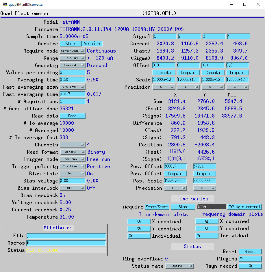
This is the medm screen to control the quadEM with the records in quadEM.template.

The example IOCs provided with quadEM load a file called commonPlugins.cmd, which loads the following set of plugins from the areaDetector module. For more information see the documentation in the links in the table below. Other plugins can also be loaded, for example the TIFF, HDF5 or Nexus file writing plugins, etc.
| Plugins loaded by commonPlugins.cmd | ||
| Plugin type | Record prefixes | Description |
|---|---|---|
| NDPluginStats | $(P)$(R)Current[1-4]: | Statistics for the current values. The average value is $(P)$(R)Current[1-4]:MeanValue_RBV. Many other statistics are available, including the minimum, maximum, standard deviation, and histogram of values. |
| NDPluginStats | $(P)$(R)Sum[X,Y,All]: | Statistics for the sum of currents 1+2, 3+4, and 1+2+3+4. The average value is $(P)$(R)Sum[X,Y,All]:MeanValue_RBV. Many other statistics are available, including the minimum, maximum, standard deviation, and histogram of values. |
| NDPluginStats | $(P)$(R)Diff[X,Y]: | Statistics for the differences of current 2-1 and 4-3. The average value is $(P)$(R)Diff[X,Y]:MeanValue_RBV. Many other statistics are available, including the minimum, maximum, standard deviation, and histogram of values. |
| NDPluginStats | $(P)$(R)Pos[X,Y]: | Statistics for the positions. The average value is $(P)$(R)Pos[X,Y]:MeanValue_RBV. Many other statistics are available, including the minimum, maximum, standard deviation, and histogram of values. |
| NDPluginStdArrays | $(P)$(R)image1: | Plugin that receives NDArray callbacks of dimension [11,NumAveraged_RBV] and puts this data into an EPICS waveform record. This can be used to provide access to all of the data from quadEM to any Channel Access client. |
| NDFileNetCDF | $(P)$(R)netCDF1: | Plugin that receives NDArray callbacks of dimension [11,NumAveraged_RBV] and writes this data into a netCDF file. This can be done in Single mode, writing one array per file. o It can also be done in Stream mode, which continuously appends arrays to a single netCDF file. |
| NDPluginTimeSeries | $(P)$(R)TS: | Plugin that receives NDArray callbacks of dimension [11,NumAveraged_RBV] and forms 11 different time-series arrays. This plugin provides a time-history (like a digital scope) of the current, sum, difference and position at speeds up to 20000Hz (TetrAMM), 6510 Hz (AH501 series), 1000Hz (AH401 series) or 813 Hz (APS_EM). The time per point can be greater than the sampling time, in which case it does averaging. The time series can operate in a fixed-length mode where acquisition stops after the specified number of time points have been collected. This mode is suited for data-acquisition applications, such as on-the-fly scanning. The time series plugin can also operate in a circular buffer mode with continuous acquisition and display of the most recent time points. This mode is suited for continuous monitoring. |
| NDPluginFFT | $(P)$(R)FFT[1-11]: | Plugin that receives the time-series arrays from the NDPluginTimeSeries plugin and computes the frequency power-spectrum of each signal. This plugin can also average the FFTs to improve the signal/noise ratio. |
Note that the first time the IOC is started all of the plugins will have EnableCallbacks=Disable. It is necessary to enable each of the plugins that will be used. The plugins will also initially start with CallbacksBlock=No. Setting CallbacksBlock=Yes can reduce CPU load on slow processors like the MVME2100 (see the performance tables below). The values of EnableCallbacks and CallbacksBlock are saved by autosave, and will be restored the next time the IOC is started.
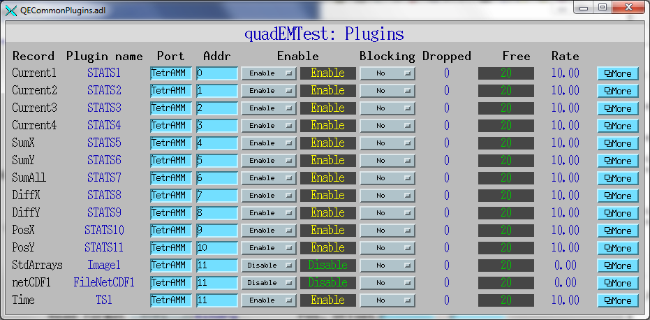
This is the medm screen for all of the plugins defined in commonPlugins.cmd.
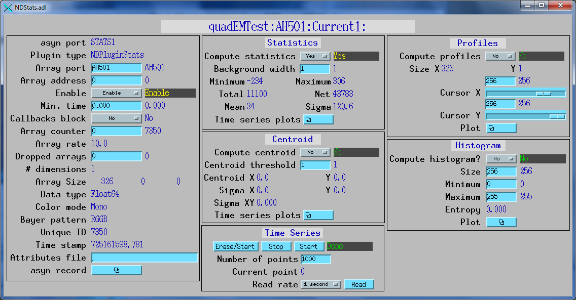
This is the medm screen for the Current1: NDPluginStats plugin loaded by commonPlugins.cmd.
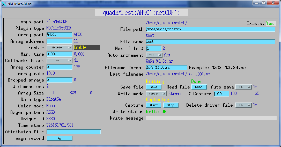
This is the medm screen for the netCDF1: NDFileNetCDF plugin loaded by commonPlugins.cmd.
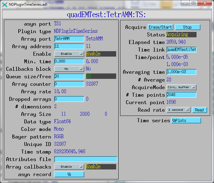
This is the medm screen to control the NDPluginTimeSeries plugin. In this example the time per point from the TetrAMM is 50 microseconds, and averaging time for the time series plugin is 1 millisecond, or 20 points. The plugin has 2000 time points, and is operating in circular buffer mode.
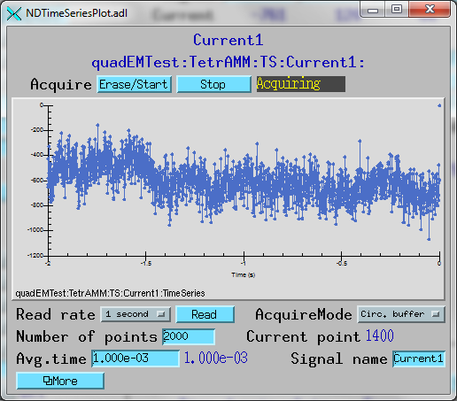
This is a plot of the time series for Current 1. It shows the last 2 seconds of data in circular buffer mode.
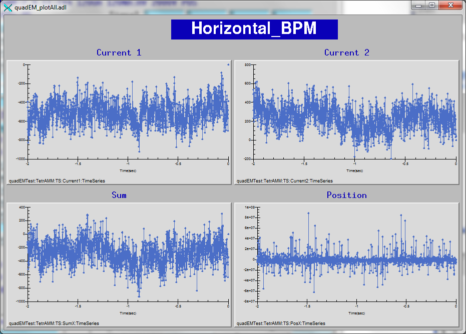
This is a plot of the time series for the horizontal currents, sum, and position. It shows the last 2 seconds of data in circular buffer mode.
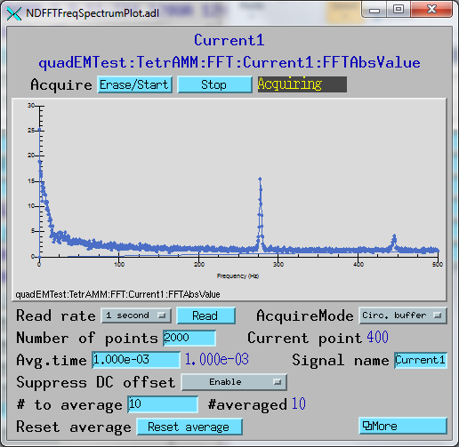
This is a plot of the FFT for Current 1. DC offset suppression is enabled and 10 FFTs are being averaged to improve the signal/noise ratio.
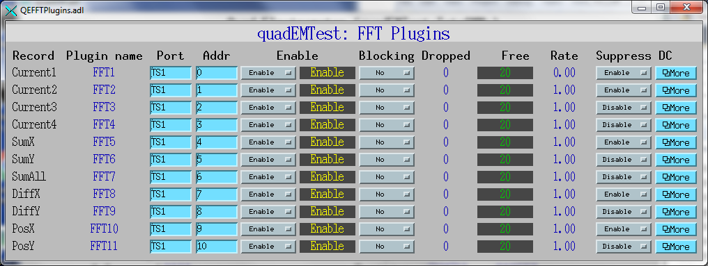
This is an medm screen for control of all 11 FFT plugins.
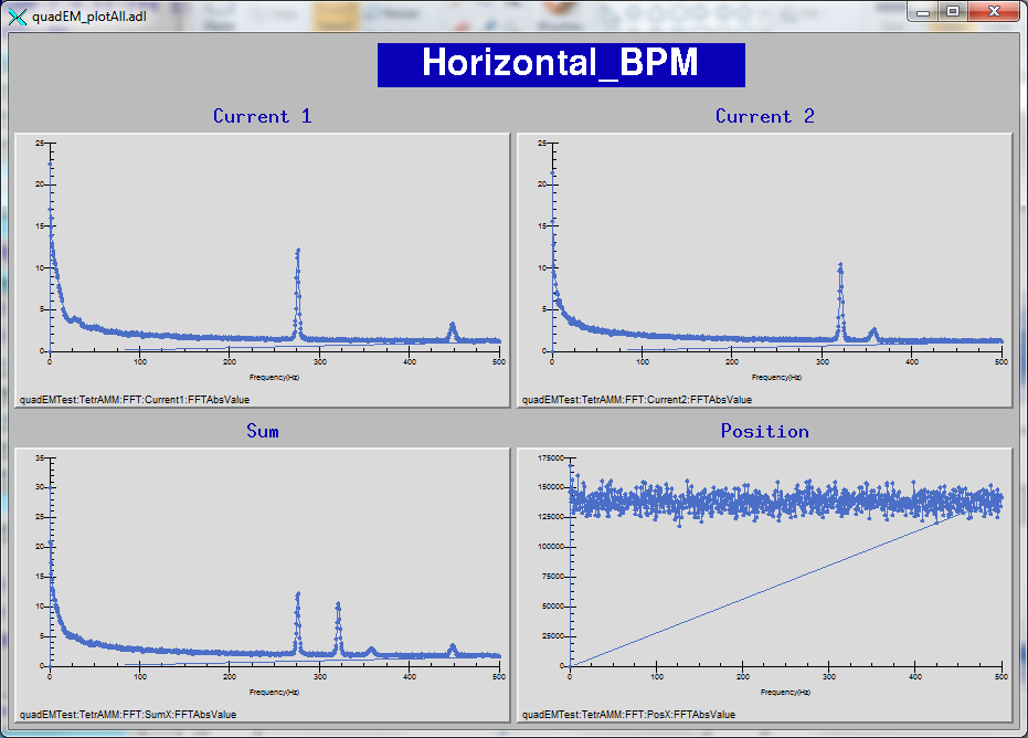
This is an medm screen that displays the FFTs of the Current, Sum, and Position for the time-series data above. 100 FFTs are being averaged to improve the signal/noise ratio.
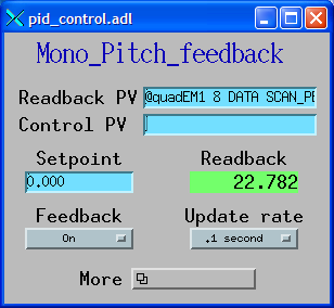
The quadEM can be used to do fast feedback with the EPID record from the synApps "std" module. The EPID record will process at up to the SampleTime discussed above. The DT field of the EPID record controls the time between feedback calculations, and this is constrained to be an integer multiple N of the quadEM SampleTime. If N>1 then N samples are averaged for each feedback operation.
This is the medm screen that controls the fast feedback of the pitch of the monochromator on APS beamline 13-ID. The readback and control PVs cannot be changed after iocInit. The update rate (SCAN rate of EPID record) only controls the rate at which the EPID record displays "snapshots" of the values of the input, output, and error. It does not affect the rate at which the feedback is actually being done, which is controlled by the DT field in the EPID record, can be much faster than the SCAN value.
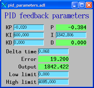
This is the medm screen that controls the PID parameters. These include the feedback coefficients KP, KI, and KD. The DT (delta time) field controls the rate at which the feedback is actually been run. In this case DT=68.0 ms, which is 55 times longer than the sampling time (1.23 ms), so 55 position readings are being averaged each time the feedback is run.
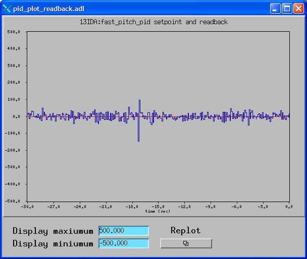
This is an medm screen that displays the setpoint of the pitch of the monochromator (in red), and the actual readback from the quadEM (in blue). Note that the readback here is only the snapshot values from the EPID record. For full-speed readings of the readback the waveform records from the quadEM_TimeSeries.template database would be used.
This is pid_fast.template, an example substitutions file. This example uses a quadEM asyn port driver named "APS_EM". ICHAN is set to read from addr=9 and 10, which are the two position values of the quadEM driver. The INPUT_DATA and INPUT_INTERVAL strings are the drvInfo strings for these parameters in the driver. The output is sent to an asyn port driver named DAC1, which is a dac128V 12-bit A/D converter in this data. OCHAN is set to write to addr=1 and 2, which are the second and third DAC channels on that card. The OUTPUT_DATA string is the drvInfo string for the double precision data in the dac128V.
file "$(STD)/stdApp/Db/fast_pid_control.db"
{
pattern
{P,                 PID,  INPUT,     INPUT_DATA,   INPUT_INTERVAL, ICHAN, OUTPUT, OCHAN,  OUTPUT_DATA,    LOPR,     HOPR,  DRVL,  DRVH,  PREC,   KP,    KI,  KD,   DT,        SCAN}
{quadEMTest:, MonoPitch, APS_EM, QE_DOUBLE_DATA,   QE_SAMPLE_TIME,     9,   DAC1,     1,  DOUBLE_DATA,  -32767,    32767,     0,  4095,     3,  .02,  100.,  0., .001, ".1 second"}
{quadEMTest:,  MonoRoll, APS_EM, QE_DOUBLE_DATA,   QE_SAMPLE_TIME,    10,   DAC1,     2,  DOUBLE_DATA,  -32767,    32767,     0,  4095,     3,  .02,  100.,  0., .001, ".1 second"}
}
The following table shows the CPU utilization of a Linux machine (Xeon E5630 2.53GHz, 8 cores), and vxWorks MVME5100, with the AH401B electometer. The CPU load was measured under the following conditions. This is the maximum data rate of the AH401B and the time series waveform records and FFTs are processing at 1 Hz.
| Performance of AH401B | ||||||
| System | %CPU time | |||||
|---|---|---|---|---|---|---|
| Linux Xeon | 6% | |||||
| MVME5100 | 15% | |||||
It can be seen that the load on the Linux machine is only 6% of a single core, while the load on the MVME5100 is 15%.
The following table shows the CPU utilization of the Linux machine and vxWorks MVME5100, with the TetrAMM electometer. The CPU load was measured under the following conditions. ValuesPerRead=5 is the maximum data rate of the AH401B and the time series waveform records and FFTs are processing at 1 Hz.
| Performance of TetrAMM | ||||||
| System | ValuesPerRead | %CPU time | ||||
|---|---|---|---|---|---|---|
| Linux Xeon | 5 | 14% | ||||
| Linux Xeon | 10 | 9% | ||||
| Linux Xeon | 20 | 6% | ||||
| Linux Xeon | 50 | 4% | ||||
| Linux Xeon | 100 | 4% | ||||
| MVME5100 | 5 | 100% | ||||
| MVME5100 | 10 | 49% | ||||
| MVME5100 | 20 | 22% | ||||
| MVME5100 | 50 | 11% | ||||
| MVME5100 | 100 | 5% | ||||
It can be seen that the worst-case load on the Linux machine is only 14% of a single core, while the load on the MVME5100 is 100% when ValuesPerRead=5. Using ValuesPerRead=20 or greater uses less than 22% of the CPU on the MVME5100, which is probably reasonable in practice. That value still produces 5 kHz updates for time-series and fast feedback.
All of the device-dependent startup scripts invoke quadEM/iocBoot/commonPlugins.cmd. This file can be edited to add additional plugins, such as the TIFF, HDF5, or Nexus file writers, etc.
Each iocBoot/iocXXX directory, e.g. iocBoot/iocTetrAMM, contains an example startup script for Linux and Windows (st.cmd) and another for vxWorks (st.cmd.vxWorks). Each of these startup scripts invokes the device-dependent startup script(s), e.g. TetrAMM.cmd, NSLS_EM.cmd, etc.
These meters communicate via IP, so they must be configured with an IP address reachable from the host IOC machine. The CAEN ELS Device Manager software must be used to configure the device IP address and port number.
An example startup script is provided in
quadEM/iocBoot/iocTetrAMM/TetraAMM.cmd
This will need to be edited to set the correct IP address of the meter to be used.
These meters communicate via IP, so they must be configured with an IP address reachable from the host IOC machine. The Lantronix module in the meters can be configured to use either UDP or TCP. UDP can reduce CPU load, however it is more susceptible to synchronization problems since it does not retransmit dropped packets. The startup script must include the UDP qualifier on the drvAsynIPPortConfigure command if UDP is selected.
Example startup scripts are provided in
quadEM/iocBoot/iocAH401B/AH401B.cmd and
quadEM/iocBoot/iocAH501/AH501.cmd
These will need to be edited to set the correct IP address of the meters to be used.
These scripts each invoke a generic script:
quadEM/iocBoot/AHxxx.cmd.
These meters communicate via IP. They only support DHCP, they cannot be given a static IP address. Each module on the subnet must have a unique Module ID, which is set by a 16-position rotary switch on the device front panel. The driver sends a broadcast message on the subnet to determine the Module ID and current IP address of all NSLS_EM modules. If the specified module ID is found then it configures communication to that module by calling drvAsynIPPortConfigure internally.
An example startup script is provided in
quadEM/iocBoot/iocNSLS_EM/NSLS_EM.cmd
This will need to be edited to set the broadcast address of the network the device is connected to, and the Module ID of the device.
These meters communicate via IP. They run the EPICS IOC software internally on the Zynq processor.
An example startup script is provided in
quadEM/iocBoot/iocNSLS2_EM/NSLS2_EM.cmd
This will need to be edited to set the Module ID of the device.
The APS_EM VME card cannot generate interrupts, but it can output a TTL pulse each time new data is available, at up to 815 Hz. If this pulse is input to an Ip-Unidig (or other asyn digital I/O device with interrupt and callback capabilities), then the ipUnidig interrupt routine will call the APS_EM driver each time new data is available. The Ip-Unidig channel where the APS_EM pulse is connected is specified in the unidigChan argument to drvAPS_EMConfigure command in the startup script. If an Ip-Unidig or other interrupt source is not being used then the APS_EM driver will poll for new data at the system clock rate, typically 60Hz.
An example startup script is provided in
quadEM/iocBoot/iocAPS_EM/APS_EM.cmd.
and
quadEM/iocBoot/iocAPS_EM/st.cmd.vxWorks.