Databases
The following tables list the database template files that are used with the LabJack modules.
Device Functions
These are the records defined in LabJack_device.template. These records provide device-wide information and control. This database is loaded once for each LabJack device.
EPICS record name |
EPICS record type |
asyn interface |
drvInfo string |
Description |
|---|---|---|---|---|
$(P)ModelName |
mbbi |
asynInt32 |
MODEL_NAME |
Device model name. mbbi values and strings are
|
$(P)FirmwareVersion |
stringin |
asynOctet |
FIRMWARE_VERSION |
Device firmware version. |
$(P)SerialNumber |
stringin |
asynOctet |
SERIAL_NUMBER |
Device serial number. |
$(P)DeviceTemperature |
ai |
asynFloat64 |
DEVICE_TEMPERATURE |
Device temperature. This is used as the cold junction reference temperature for thermocouple measurements. It has SCAN=”5 second” which is fast enough for this slowly varying value. |
$(P)LJMVersion |
stringin |
asynOctet |
LJM_VERSION |
Version of the LabJack LJM library. |
$(P)DriverVersion |
stringin |
asynOctet |
DRIVER_VERSION |
Version of the EPICS driver. |
$(P)LastErrorMessage |
waveform |
asynOctet |
LAST_ERROR_MESSAGE |
The last error message from the driver. This includes a timestamp. |
$(P)PollSleepMS |
ao |
asynFloat64 |
POLL_SLEEP_MS |
The number of milliseconds to sleep at the end of each poll cycle. |
$(P)PollTimeMS |
ai |
asynFloat64 |
POLL_TIME_MS |
The actual number of milliseconds to execute the poll cycle, including the sleep. |
$(P)AiAllSettlingUS |
ao |
asynFloat64 |
ANALOG_IN_SETTLING_TIME_ALL |
Selects the settling time for all analog input channels. |
$(P)AiAllResolution |
mbbo |
asynInt32 |
ANALOG_IN_RESOLUTION_ALL |
High values of resolution result in lower noise and longer ADC conversion time. Resolution 0 is the default resolution for that model.
|
$(P)AiSamplingRate |
ao |
asynFloat64 |
ANALOG_IN_SAMPLING_RATE |
This sets the sampling rate of the ADC in Hz.
|
$(P)DeviceReset |
bo |
asynInt32 |
DEVICE_RESET |
Processing this record sets the device watchdog time to 10 s, and the watchdog timer function to device reset. This will reset the device after 10 seconds of communications inactivity. Processing this record, exiting the IOC application, and waiting at least 10 seconds will cause the device to reset. This can be used to remotely recover from a device malfunction that requires a reset. Note that the device will continue to reset every 10 seconds until the IOC successfully starts again. The IOC may occasionally fail to start after a DeviceReset because the device is currently resetting. Trying again will eventually succeed. |
Analog Input Functions
These are the records defined in LabJack_ai.template. This database is loaded once for each analog input channel
EPICS record name |
EPICS record type |
asyn interface |
drvInfo string |
Description |
|---|---|---|---|---|
$(P)Ai$(N) |
ai |
asynFloat64 |
ANALOG_IN_VALUE |
Analog input value. This is polled in the driver, so either period or I/O Intr scanning can be used. |
$(P)AiEnable$(N) |
bo |
asynInt32 |
ANALOG_IN_ENABLE |
Enable flag for this analog input channel. Disabled inputs are not read by the poller. Unconnected inputs should be disabled to improve accuracy on active channels and to reduce the polling time. |
$(P)AiMode$(N) |
mbbo |
asynInt32 |
ANALOG_IN_MODE |
Input mode for this analog input channel. Choices are Volts and 9 different thermocouple types. |
$(P)AiTempUnits$(N) |
mbbo |
asynInt32 |
TEMPERATURE_UNITS |
Temperature units for this analog input channel if a thermocouple mode is selected. Choices are “K”, “C”, and “F”. |
$(P)AiDiff$(N) |
mbbo |
asynInt32 |
ANALOG_IN_DIFF |
Selects “Single-Ended” or “Differential” input mode on the T7 and T7-PRO. The T4 is always single-ended and the T8 is always differential. The driver constructs the strings and values based on the model. |
$(P)AiRange$(N) |
mbbo |
asynInt32 |
ANALOG_IN_RANGE |
Selects the input range for this analog input channel.
The driver constructs the strings and values based on the model. |
$(P)AiResolution$(N) |
mbbo |
asynInt32 |
ANALOG_IN_RESOLUTION |
Selects the input resolution for this analog input channel. High values of resolution result in lower noise and longer ADC conversion time.
|
The following is the medm screen for controlling the analog input configuration records.
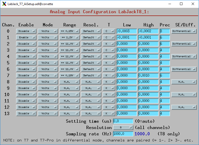
LabJack_T7_AiSetup.adl
While this screen is nominally specific to the T7 and T7-PRO, it can be used for any model. On the T8 analog inputs 8-13 do not apply and the inputs are always in Differential mode. On the T4 analog inputs 12-13 do not apply. Thermocouples only work well with the T7-PRO in 24-bit mode (resolutions 9-12), or with the T8 with low-voltage ranges. They do not work well with the T4 or T7.
Analog Output Functions
These are the records defined in LabJack_Ao.template. This database is loaded once for each analog output channel
EPICS record name |
EPICS record type |
asyn interface |
drvInfo string |
Description |
|---|---|---|---|---|
$(P)$(R) |
ao |
asynFloat64 |
ANALOG_OUT_VALUE |
Analog output value. |
$(P)$(R)TweakVal |
ao |
N.A. |
N.A. |
The amount by which to tweak the out when the Tweak record is processed. |
$(P)$(R)TweakUp |
calcout |
N.A. |
N.A. |
Tweaks the output up by TweakVal. |
$(P)$(R)TweakDown |
calcout |
N.A. |
N.A. |
Tweaks the output down by TweakVal. |
The following is the medm screen for configuring the analog output records. The drive limits can be more restrictive than the full output range of the analog outputs.
Channels 0 and 1 are the on-board DACs on all models. The range is 0-5V for the on-board DACs on the T4, T7, and T7-PRO, and 0-10V on the T8.
Channels 2 and above are the LJTick DACs that can be optionally installed on any model. The range on the LJTick DACs is +-10V.
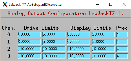
LabJack_T7_AoSetup.adl
The following is the medm screen for controlling the optional LJTick DACs.
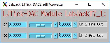
LabJack_LJTick_DAC2.adl
Digital I/O Functions
These are the records defined in LabJack_binary.template and LabJack_biWord.template.
EPICS record name |
EPICS record type |
asyn interface |
drvInfo string |
Description |
|---|---|---|---|---|
$(P)Bi$(N) |
bi |
asynUInt32Digital |
DIGITAL_IN_WORD |
Digital input value. The MASK parameter in the INP link defines which bit is used. The binary inputs are polled by the driver poller thread, so these records should have SCAN=”I/O Intr”. |
$(P)Bo$(N) |
bo |
asynUInt32Digital |
DIGITAL_OUT_BIT |
Digital output value. The ADDR parameter in the INP link defines which bit is used. |
$(P)Bd$(N) |
bo |
asynUInt32Digital |
DIGITAL_DIRECTION |
Direction of this I/O line, “In” (0) or “Out” (1). The MASK parameter in the INP link defines which bit is used. |
$(P)$(R) |
longin |
asynUInt32Digital |
DIGITAL_INPUT |
Digital input value as a word, rather than individual bits. The ADDR parameter in the INP link defines which word is read. 0=DIO (bits 0-23), 1=FIO (bits 0-7), 2=EIO (bits 8-15), 3=CIO (bits 16-19), and 4=MIO (bits 20-22). The binary inputs are polled by the driver poller thread, so these records should have SCAN=”I/O Intr”. |
Waveform Digitizer Functions
These records are defined in the following files: - LabJack_waveformDig.template. This database is loaded once per module. - LabJack_waveformDigN.template. This database is loaded for each digitizer input channel.
EPICS record name |
EPICS record type |
asyn interface |
drvInfo string |
Description |
|---|---|---|---|---|
$(P)WaveDigNumPoints |
longout |
asynInt32 |
WAVEDIG_NUM_POINTS |
Number of points to digitize. This cannot be more than the value of maxInputPoints that was specified in LabJackConfig. |
$(P)WaveDigFirstChan |
mbbo |
asynInt32 |
WAVEDIG_FIRST_CHAN |
First channel to digitize, 0-13. |
$(P)WaveDigNumChans |
mbbo |
asynInt32 |
WAVEDIG_NUM_CHANS |
Number of channels to digitize. 1-14. The maximum valid number is 13-FirstChan+1. |
$(P)WaveDigTimeWF |
waveform |
asynFloat32Array |
WAVEDIG_TIME_WF |
Timebase waveform. These values are calculated when Dwell or NumPoints are changed. It is typically used as the X-axis in plots. |
$(P)WaveDigCurrentPoint |
longin |
asynInt32 |
WAVEDIG_CURRENT_POINT |
The current point being collected. This does not always increment by 1 because the device can transfer data in blocks. |
$(P)WaveDigDwell |
ao |
asynFloat64 |
WAVEDIG_DWELL |
The time per point in seconds. The minimum time depends on the device type and NumChans. |
$(P)WaveDigDwellActual |
ai |
asynFloat64 |
WAVEDIG_DWELL_ACTUAL |
The actual time per point in seconds. This may differ from the requested Dwell because of clock granularity in the device. |
$(P)WaveDigTotalTime |
ai |
asynFloat64 |
WAVEDIG_TOTAL_TIME |
The total time to digitize NumChans*NumPoints. |
$(P)WaveDigResolution |
mbbo |
asynInt32 |
WAVEDIG_RESOLUTION |
The ADC resolution to use for all channels during the scan. The choices are model-dependent and are set by the driver. |
$(P)WaveDigSettlingTime |
ao |
asynFloat64 |
WAVEDIG_SETTLING_TIME |
The ADC settling time in microseconds to use for all channels during the scan. 0 selects the device default. |
$(P)WaveDigExtTrigger |
bo |
asynInt32 |
WAVEDIG_EXT_TRIGGER |
The trigger source, “Internal” (0) or “External” (1). NOTE: NOT YET IMPLEMENTED. |
$(P)WaveDigExtClock |
bo |
asynInt32 |
WAVEDIG_EXT_CLOCK |
The clock source, “Internal” (0) or “External” (1). If External is used then the Dwell record does not control the digitization rate, it is controlled by the external clock. However Dwell should be set to approximately the correct value if possible, because that builds the time axis for plotting. NOTE: NOT YET IMPLEMENTED. |
$(P)WaveDigAutoRestart |
bo |
asynInt32 |
WAVEDIG_AUTO_RESTART |
Values are “Disable” (0) and “Enable” (1). This controls whether the driver automatically starts another acquire when the previous one completes. |
$(P)WaveDigRun |
busy |
asynInt32 |
WAVEDIG_RUN |
Values are “Stop” (0) and “Run” (1). This starts and stops the waveform digitizer. It will automatically stop when the requested number of samples have been acquired. |
$(P)WaveDigReadWF |
busy |
asynInt32 |
WAVEDIG_READ_WF |
Values are “Done” (0) and “Read” (1). This reads the waveform data from the device buffers into the waveform records. Note that the driver always reads device when acquisition stops, so for quick acquisitions this record can be Passive. To see partial data during long acquisitions this record can be periodically processed. |
$(P)WaveDigVoltWF$(N) |
waveform |
asynFloat64Array |
WAVEDIG_VOLT_WF |
This waveform record contains the digitizer waveform data for channel N. This record has scan=I/O Intr, and it will process whenever acquisition completes, or whenever the ReadWF record above processes. The data are in volts or temperature units. |
This is the medm screen that controls the waveform digitizer.
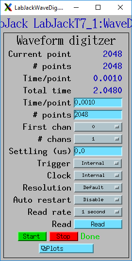
LabJackWaveDig.adl
This is a plot of the waveform digitizer waveform for analog input 0 capturing 1000 samples/s (Dwell=0.001).
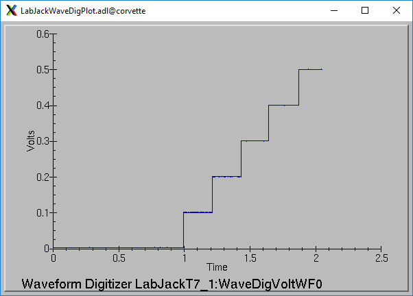
LabJackWaveDigPlot.adl
Waveform Generator Functions
These records are defined in the following files: - LabJack_waveformGen.template. This database is loaded once per module. - LabJack_waveformGenN.template. This database is loaded for each waveform generator output channel.
EPICS record name |
EPICS record type |
asyn interface |
drvInfo string |
Description |
|---|---|---|---|---|
$(P)WaveGenNumPoints |
longin |
asynInt32 |
WAVEGEN_NUM_POINTS |
Number of points output waveform. The value of this record is equal to UserNumPoints if user-defined waveforms are selected, or IntNumPoints if internal predefined waveforms are selected. |
$(P)WaveGenUserNumPoints |
longout |
asynInt32 |
WAVEGEN_USER_NUM_POINTS |
Number of points in user-defined output waveforms. This cannot be more than the value of maxOutputPoints that was specified in LabJackConfig. |
$(P)WaveGenIntNumPoints |
longout |
asynInt32 |
WAVEGEN_INT_NUM_POINTS |
Number of points in internal predefined output waveforms. This cannot be more than the value of maxOutputPoints that was specified in LabJackConfig. |
$(P)WaveGenUserTimeWF |
waveform |
asynFloat32Array |
WAVEDIG_USER_TIME_WF |
Timebase waveform for user-defined waveforms. These values are calculated when UserDwell or UserNumPoints are changed. It is typically used as the X-axis in plots. |
$(P)WaveGenIntTimeWF |
waveform |
asynFloat32Array |
WAVEGEN_INT_TIME_WF |
Timebase waveform for internal predefined waveforms. These values are calculated when IntDwell or IntNumPoints are changed. It is typically used as the X-axis in plots. |
$(P)WaveGenCurrentPoint |
longin |
asynInt32 |
WAVEGEN_CURRENT_POINT |
The current point being output. This does not always increment by 1 because the device can transfer data in blocks. |
$(P)WaveGenFrequency |
ai |
asynFloat64 |
WAVEGEN_FREQUENCY |
The output frequency (waveforms/second). The value of this record is equal to UserFrequency if user-defined waveforms are selected, or IntFrequency if internal predefined waveforms are selected. |
$(P)WaveGenDwell |
ai |
asynFloat64 |
WAVEGEN_DWELL |
The output dwell time or period (seconds/sample). The value of this record is equal to UserDwell if user-defined waveforms are selected, or IntDwell if internal predefined waveforms are selected. |
$(P)WaveGenDwellActual |
ai |
asynFloat64 |
WAVEGEN_DWELL_ACTUAL |
The actual dwell time. This can be different from the requested dwell time (WaveGenDwell) because of the granularity of the device clock. |
$(P)WaveGenUserDwell |
ao |
asynFloat64 |
WAVEGEN_USER_DWELL |
The output dwell time or period (seconds/sample) for user-defined waveforms. This record is automatically changed if UserFrequency is modified. |
$(P)WaveGenIntDwell |
ao |
asynFloat64 |
WAVEGEN_INT_DWELL |
The output dwell time or period (seconds/sample) for internal predefined waveforms. This record is automatically changed if IntFrequency is modified. |
$(P)WaveGenUserFrequency |
ao |
N.A. |
N.A. |
The output frequency (waveforms/second) for user-defined waveforms. This record computes UserDwell and writes to that record. This record is automatically changed if UserDwell is modified. |
$(P)WaveGenIntFrequency |
ao |
N.A. |
N.A. |
The output frequency (waveforms/second) for internal predefined waveforms. This record computes IntDwell and writes to that record. This record is automatically changed if IntDwell is modified. |
$(P)WaveGenTotalTime |
ai |
asynFloat64 |
WAVEGEN_TOTAL_TIME |
The total time to output the waveforms. This is WaveGenDwellActual*NumPoints. |
$(P)WaveGenExtTrigger |
bo |
asynInt32 |
WAVEGEN_EXT_TRIGGER |
The trigger source, “Internal” (0) or “External” (1). NOTE: NOT YET IMPLEMENTED, |
$(P)WaveGenExtClock |
bo |
asynInt32 |
WAVEGEN_EXT_CLOCK |
The clock source, “Internal” (0) or “External” (1). If External is used then the Dwell record does not control the output rate, it is controlled by the external clock. However Dwell should be set to approximately the correct value if possible, because that controls the time axis on the plots. NOTE: NOT YET IMPLEMENTED. |
$(P)WaveGenContinuous |
bo |
asynInt32 |
WAVEGEN_CONTINUOUS |
Values are “One-shot” (0) or “Continuous” (1). This controls whether the device stops when the output waveform is complete, or immediately begins again at the start of the waveform. |
$(P)WaveGenRun |
busy |
asynInt32 |
WAVEGEN_RUN |
Values are “Stop” (0) and “Run” (1). This starts and stops the waveform generator. In one-shot mode the waveform generator stops automatically when all of the samples have been output. |
$(P)WaveGenUserWF$(N) |
waveform |
asynFloat64Array |
WAVEGEN_USER_WF |
This waveform record contains the user-defined waveform generator data for channel N. The data are in volts. These data are typically generated by an EPICS Channel Access client. |
$(P)WaveGenInternalWF$(N) |
waveform |
asynFloat64Array |
WAVEGEN_INT_WF |
This waveform record contains the internal predefined waveform generator data for channel N. The data are in volts. |
$(P)WaveGenEnable$(N) |
bo |
asynInt32 |
WAVEGEN_ENABLE |
Values are “Disable” and “Enable”. Controls whether channel N output is enabled. |
$(P)WaveGenType$(N) |
mbbo |
asynInt32 |
WAVEGEN_WAVE_TYPE |
Controls the waveform type on channel N. Values are
Note that if any channel is “User-defined” then all channels must be. Note that all internally predefined waveforms are symmetric about 0 volts. To output unipolar signals the Offset should be set to +-Amplitude/2. |
$(P)WaveGenPulseWidth$(N) |
ao |
asynFloat64 |
WAVEGEN_PULSE_WIDTH |
Controls the pulse width in seconds if Type is “Pulse”. |
$(P)WaveGenAmplitude$(N) |
ao |
asynFloat64 |
WAVEGEN_AMPLITUDE |
Controls the amplitude of the waveform. For internally predefined waveforms this directly controls the peak-to-peak amplitude in volts. For user-defined waveforms this is a scale factor that multiplies the values in the waveform, i.e. 1.0 outputs the user-defined waveform unchanged, 2.0 increases the amplitide by 2, etc. For both internal and used-defined waveforms changing the sign of the Amplitude controls the polarity of the signal. |
$(P)WaveGenOffset$(N) |
ao |
asynFloat64 |
WAVEGEN_OFFSET |
Controls the offset of the waveform in volts. For user-defined waveforms, this value is added to the waveform, i.e. 0.0 outputs the user-defined waveform unchanged, 1.0 adds 1 volt, etc. |
This is the medm screen for the waveform generator.
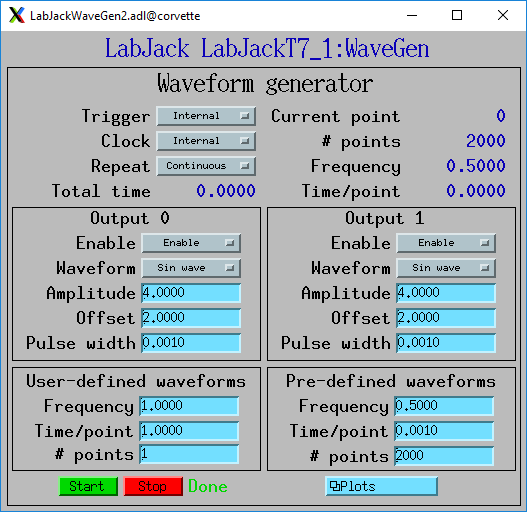
LabJackWaveGen2.adl
This is a plot of an internal predefined sin wave waveform.
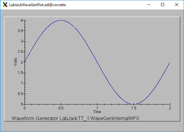
Plot of an internal predefined waveform (sin wave)