
User Guide
Table of contents
IOC Startup
Using the iocsh snippet
The recommended way to configure Love controllers is with the love.iocsh snippet. It handles serial port configuration, driver initialization, and database loading for each controller instance.
iocshLoad("$(LOVE)/iocsh/love.iocsh", "PREFIX=ioc:, PORT=L0, SERIAL=S0, ADDR=0x01, INSTANCE=Love1, MODEL=1600")
iocshLoad("$(LOVE)/iocsh/love.iocsh", "PREFIX=ioc:, PORT=L0, SERIAL=S0, ADDR=0x02, INSTANCE=Love2, MODEL=16A")
The snippet macros are:
| Macro | Description |
|---|---|
PREFIX | IOC PV prefix |
PORT | Name for the Love driver’s asyn port |
SERIAL | Name of the asyn serial port (only needed for the first controller on a given port) |
ADDR | Controller address on the RS-485 bus (hex) |
INSTANCE | Controller instance name, used as a PV name component |
MODEL | Controller model: 1600 or 16A |
The serial port must be configured with drvAsynSerialPortConfigure before the first iocshLoad call for a given PORT. The snippet automatically sets serial options (19200 baud, 8N1, no flow control) and calls drvLoveInit on the first invocation for each port.
Manual configuration
For direct control over initialization, use the iocsh commands individually. An asyn serial port must be configured first:
drvAsynSerialPortConfigure("S0", "/dev/ttyS0", 0, 0, 0)
asynSetOption("S0", 0, "baud", "19200")
asynSetOption("S0", 0, "bits", "8")
asynSetOption("S0", 0, "parity", "none")
asynSetOption("S0", 0, "stop", "1")
asynSetOption("S0", 0, "clocal", "Y")
asynSetOption("S0", 0, "crtscts", "N")
Then initialize the Love driver and configure each controller:
drvLoveInit("L0", "S0", 0)
drvLoveConfig("L0", 0x01, "1600")
drvLoveConfig("L0", 0x02, "1600")
drvLoveConfig("L0", 0x03, "16A")
drvLoveInit creates the asyn port driver and connects it to the serial port. drvLoveConfig registers a controller at the given address (1–256, hex) with the specified model.
After configuration, load the database records for each controller:
dbLoadRecords("$(LOVE)/db/LoveController.db", "P=ioc:, Q=Love1:, PORT=L0, ADDR=0x01")
dbLoadRecords("$(LOVE)/db/LoveControllerControl.db", "P=ioc:, Q=Love1:, PORT=L0, ADDR=0x01")
An example IOC is provided under iocs/loveExIOC/. See the startup scripts in iocs/loveExIOC/iocBoot/ioclove/ for complete Linux and vxWorks examples.
Database
The database consists of records for reading and controlling values on the Love controllers. Two database files are provided:
| File | Description |
|---|---|
LoveController.db | Read-back records: value, set points, alarm limits, peak, valley, communication status |
LoveControllerControl.db | Configuration records: set point and alarm limit adjustment |
Both files use the following macros:
| Macro | Description |
|---|---|
P | PV prefix (e.g., ioc:) |
Q | Controller instance qualifier (e.g., Love1:) |
PORT | Love driver asyn port name |
ADDR | Controller address (hex) |
Records are organized into three categories:
- Base records read integer values directly from the controller (decimal points, set points, alarm limits, status).
- Composite records (calc records) combine base record values to produce floating-point representations. For example, a set point calc record uses the decimal points value and the raw set point integer to compute the actual set point.
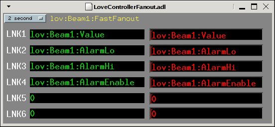
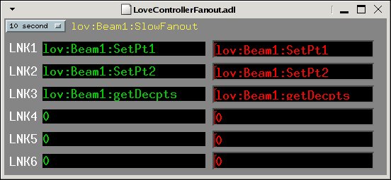
- Fanout records drive the processing rate of the base and composite records. Two fanout records provide fast and slow processing rates, adjustable from the MEDM screens.
The
getDecptsPV must remain in the fast fanout record at all times. This value is required by many PVs to derive their floating-point values.
A save/restore request file (Love_settings.req) is also provided for use with autosave.
Operator Screens
The module includes operator interface screens in three formats: MEDM (.adl), CSS-BOY (.opi), and caQtDM (.ui).
The main controller screen displays read-back values, set points, alarm limits, and alarm status. An ENABLE menu allows disabling/enabling record processing.
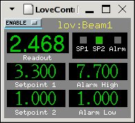
A hidden menu in the upper right corner of the main screen opens the control display, which shows additional values (input type, communication status) and allows adjustment of configuration parameters such as set point 1 and scan rate.
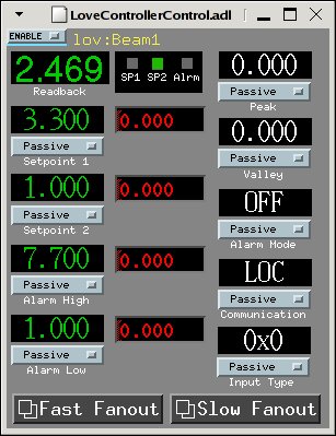
The “Fast Fanout” and “Slow Fanout” buttons launch screens that list the PVs being acquired and their processing rate. Users can add PVs or change the rate at runtime.
Changes made to fanout records at runtime are not preserved across IOC reboots. Modify the database records directly to make permanent changes.
Wiring
Communication with the controllers uses half-duplex RS-485. An RS-232 to RS-485 converter is required. See the WIRING file for detailed pinout and wiring diagrams for a typical setup using the B&B Electronics 485LDRC converter.
Files
Source
| File | Description |
|---|---|
loveApp/src/drvLove.c | Asyn multi-device port driver |
loveApp/src/devLove.dbd | DBD file for importing Love support into other applications |
Database
| File | Description |
|---|---|
loveApp/Db/LoveController.db | Read-back records |
loveApp/Db/LoveControllerControl.db | Configuration records |
loveApp/Db/Love_settings.req | Autosave request file |
IOC Shell
| File | Description |
|---|---|
loveApp/iocsh/love.iocsh | Reusable iocsh snippet for configuring a controller instance |
Example IOC
| File | Description |
|---|---|
iocs/loveExIOC/iocBoot/ioclove/st.cmd.linux | Linux startup script |
iocs/loveExIOC/iocBoot/ioclove/st.cmd.vx | vxWorks startup script |
Hardware Documentation
| Directory | Contents |
|---|---|
docs/1600/ | Model 1600 user manual, communication protocol, calibration |
docs/16A/ | Model 16A user manual, communication protocol, data sheet, calibration, flow chart |
docs/485LDRC/ | RS-232 to RS-485 converter data sheet, wiring and installation diagrams |