Driver for Multi-Function Devices
- author:
Mark Rivers, University of Chicago
Introduction
This is an EPICS driver for the multi-function devices from MeasurementComputing. These multi-function devices support support analog input, temperature input (thermocouple, RTD, thermistor, and semiconductor), analog output, binary I/O, counters, and timers. Not all devices have all of these capabilities.
The driver is written in C++, and consists of a class that inherits from asynPortDriver, which is part of the EPICS asyn module.
The driver is written to be general, so that it can be used with any Measurement Computing multi-function module. It uses the introspection capabilities of their UL library to query many of the device features. However, there are some features that cannot be queried, so the driver does require small modifications to be be used with a new model.
Supported models
The following models are currently supported.
E-1608
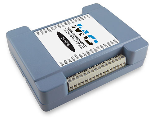
Photo of E-1608
This module costs $525 and has the following features:
16-bit analog inputs
8 single-ended channels or 4 differential channels
Programmable per-channel range: +-1V, +-2V, +-5V, +-10V
250 kHz total maximum input rate, i.e. 1 channel at 250 kHz, 2 channels at 125 kHz, etc.
Internal or external trigger.
Internal or external clock for input signals.
Input FIFO, unlimited waveform length
16-bit analog outputs
2 channels, fixed +-10V range
No output waveform capability
Digital inputs/outputs
8 signals, individually programmable as inputs or outputs
Counter
1 input
10 MHz maximum rate, 32-bit register
More information can be found in the E-1608 product description.
The following is the main medm screen for controlling the E-1608.
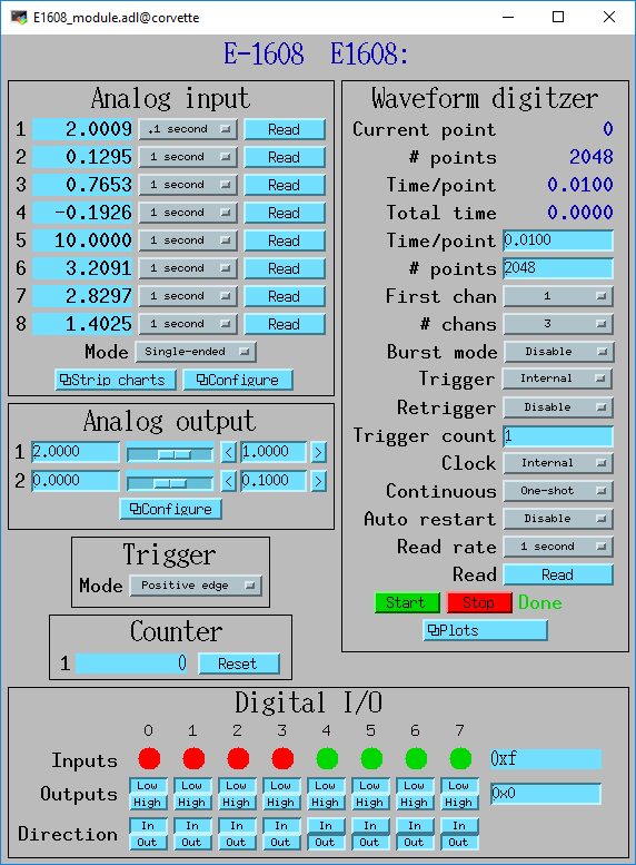
E1608_module.adl
E-TC
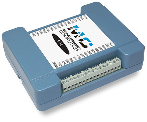
Photo of E-TC
This module costs $505 and has the following features:
Ethernet interface.
8 thermocouple inputs
8 channels with cold-junction compensation. Types J, K, T, E, R, S, B, and N.
4 samples/s.
Digital inputs/outputs
8 signals, individually programmable as inputs or outputs
Counters
1 input
10 MHz maximum rate, 32-bit register
More information can be found in the E-TC product description.
The following is the main medm screen for controlling the E-TC.
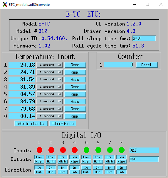
ETC_module.adl
TC-32
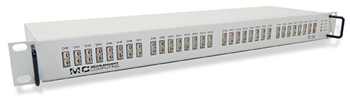
Photo of TC-32
This module costs $1999 and has the following features:
USB and Ethernet interfaces, either can be used.
32 thermocouple inputs
32 channels with cold-junction compensation. Types J, K, T, E, R, S, B, and N.
3 samples/s if reading all 32 channels, faster if reading fewer.
Digital inputs
8 digital inputs, switch-selectable pullup resistor
Digital outputs
32 digital inputs, switch-selectable pullup resistor
Each output can either be controlled by software or can be controlled by the alarm status of the corresponding thermocouple. Flexible alarm configuration, i.e. hysteresis.
More information can be found in the TC-32 product description.
The following is the main medm screen for controlling the TC-32.
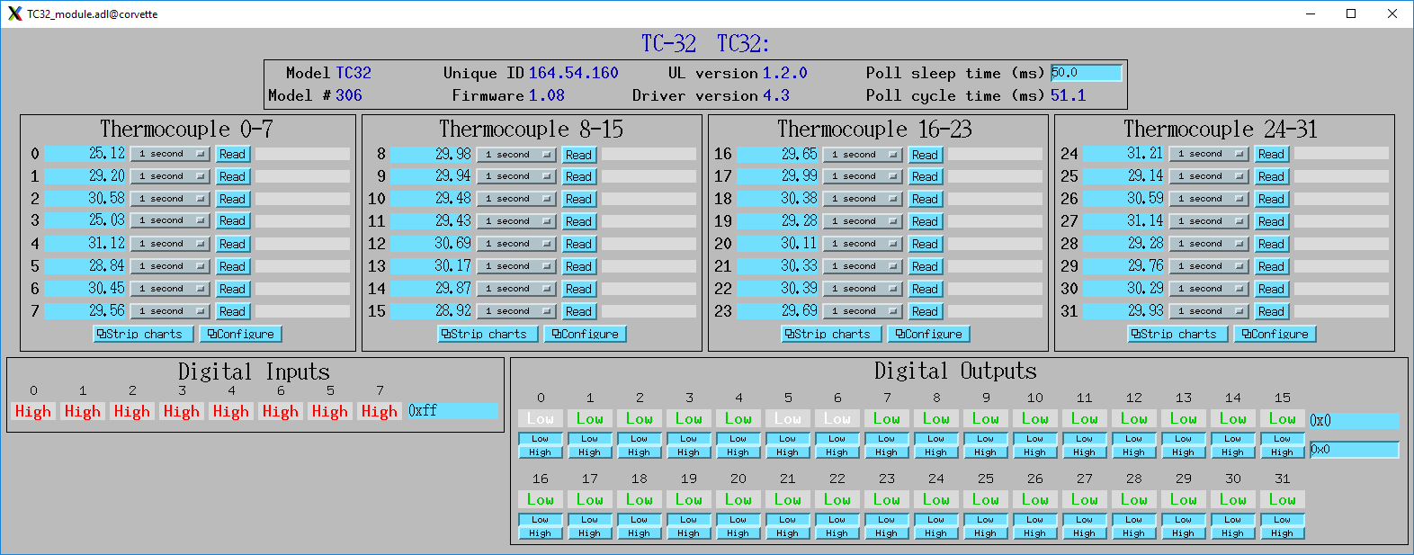
TC32_module.adl
USB-1608G and USB-1608GX-2AO
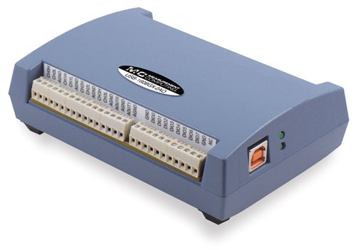
Photo of USB-1608GX-2AO
This module costs $799 and has the following features:
16-bit analog inputs
16 single-ended channels or 8 differential channels
Programmable per-channel range: +-1V, +-2V, +-5V, +-10V
500 kHz total maximum input rate, i.e. 1 channel at 500 kHz, 8 channels at 62.5 kHz, etc.
Internal or external trigger. External trigger shared with analog outputs.
Internal or external clock, input and output signals.
4 kSample input FIFO, unlimited waveform length
16-bit analog outputs
2 channels, fixed +-10V range
500 kHz total maximum output rate, i.e. 1 channel at 500 kHz, 2 channels at 250 kHz
Internal or external trigger. External trigger shared with analog inputs.
Internal or external clock, input and output signals
2 kSample output FIFO, unlimited waveform length
Digital inputs/outputs
8 signals, individually programmable as inputs or outputs
Pulse generator
1 output
64MHz clock, 32-bit registers
Programmable period, width, number of pulses, polarity
Counters
2 inputs
20 MHz maximum rate, 32-bit registers
More information can be found in the USB-1608GX-2AO product description.
The USB-1608G is very similar to the USB-1608GX-2AO except that it does not have any analog outputs and the analog inputs are limited to 250 kHz rather than 500 kHz. More information can be found in the USB-1608G product description.
The following is the main medm screen for controlling the USB-1608GX-2AO.
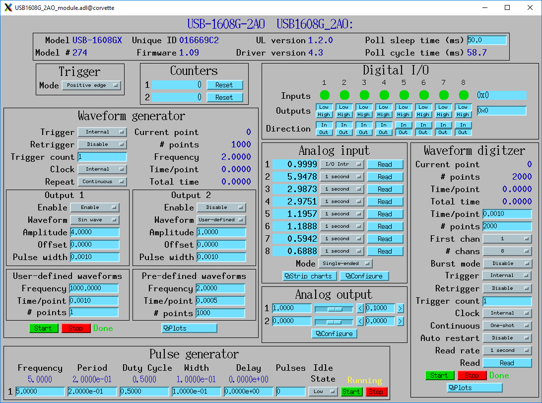
1608G_module.adl
USB-1808 and USB-1808X
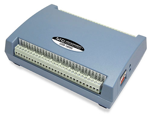
Photo of USB-1808
These modules cost $769 and $989 and have the following features:
18-bit analog inputs
8 single-ended or differential channels
Programmable per-channel range:+-5V, +-10V, 0-5V, 0-10V
USB-1808: 125 kHz total maximum input rate, i.e. 1 channel at 125 kHz, 8 channels at 15.625 kHz, etc.
USB-1808X: 500 kHz total maximum input rate, i.e. 1 channel at 500 kHz, 8 channels at 62.5 kHz, etc.
Internal or external trigger. External trigger shared with analog outputs.
Internal or external clock, input and output signals.
4 kSample input FIFO, unlimited waveform length
16-bit analog outputs
2 channels, fixed +-10V range
USB-1808: 250 kHz total maximum output rate, i.e. 1 channel at 250 kHz, 2 channels at 125 kHz
USB-1808X: 1000 kHz total maximum output rate, i.e. 1 channel at 1000 kHz, 2 channels at 500 kHz
Internal or external trigger. External trigger shared with analog inputs.
Internal or external clock, input and output signals
2 kSample output FIFO, unlimited waveform length
Digital inputs/outputs
4 signals, individually programmable as inputs or outputs
Pulse generator
2 outputs
100 MHz clock, 32-bit registers
Programmable period, width, number of pulses, polarity
Counters
2 inputs
50 MHz maximum rate, 32-bit registers
Quadrature encoder inputs
2 inputs
50 MHz maximum rate, 32-bit registers
More information can be found in the USB-1808 product description.
The following is the main medm screen for controlling the USB-1808.
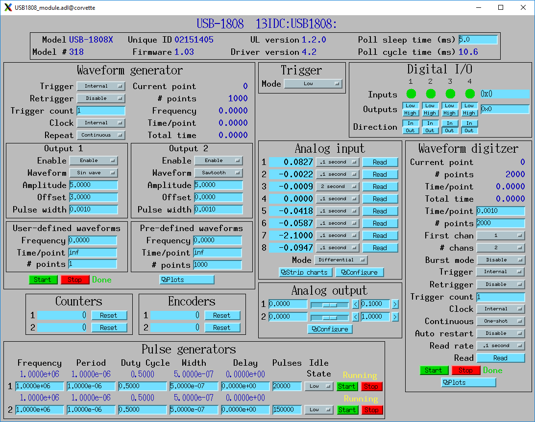
1808_module.adl
USB-2408-2AO
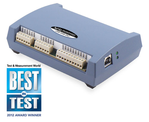
Photo of Photo of USB-2408-2AO
This module costs $699 and has the following features:
24-bit analog inputs
16 single-ended channels or 8 differential channels
Programmable per-channel range: 8 ranges from +-0.078V to +-10V
Thermocouple support for 8 channels with cold-junction compensation. Types J, K, T, E, R, S, B, or N.
1 kHz total maximum input rate, i.e. 1 channel at 1 kHz, 8 channels at 125 Hz, etc.
Input FIFO, unlimited waveform length
16-bit analog outputs
2 channels, fixed +-10V range
1000 Hz total maximum output rate, i.e. 1 channel at 1000 Hz, 2 channels at 500 Hz
Output FIFO, unlimited waveform length
Digital inputs/outputs
8 signals, individually programmable as inputs or outputs
Counters
2 inputs
1 MHz maximum rate, 32-bit registers
More information can be found in the USB-2408-2AO product description.
The following is the main medm screen for controlling the USB-2408-2AO.
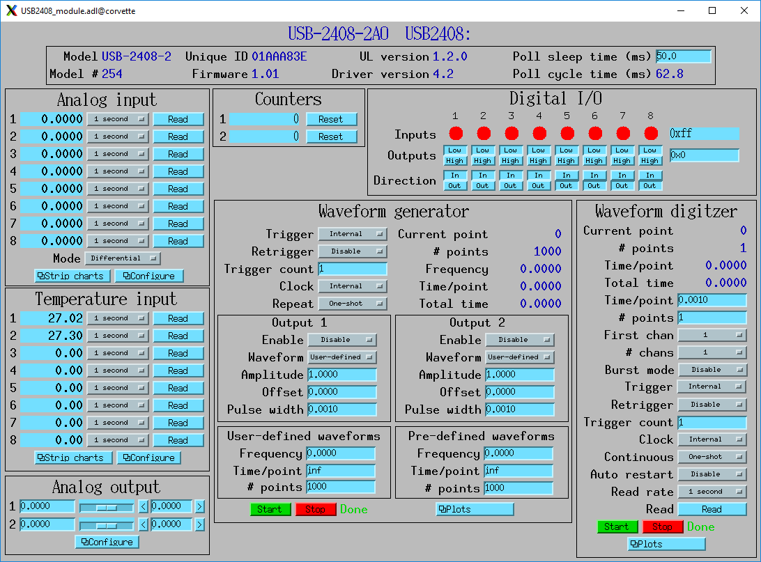
2408_module.adl
USB-TEMP and USB-TEMP-AI
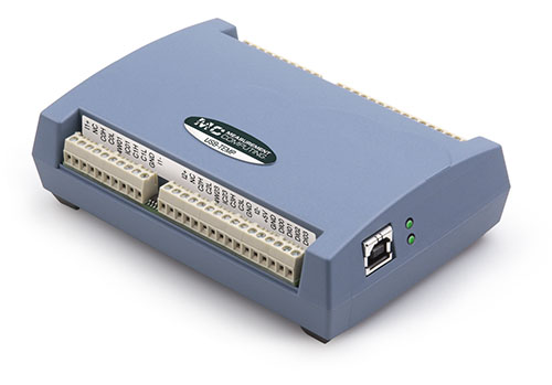
Photo of Photo of USB-TEMP
The USB-TEMP costs $605 and the USB-TEMP-AI costs $795. They have the following features:
Temperature inputs
8 temperature inputs on USB-TEMP, 4 on USB-TEMP-AI. These can be platinum resistance thermometers (RTD), thermocouples, thermistors, or semiconductor sensors.
Thermocouple support has cold-junction compensation. Types J, K, T, E, R, S, B, or N.
2 samples/s per channel.
24-bit analog inputs (USB-TEMP-AI only)
4 channels
Programmable per-channel range: 4 ranges from +-1.25V to +-10V
Digital inputs/outputs
8 signals, individually programmable as inputs or outputs
Counters
1 input
1 MHz maximum rate, 32-bit register
More information can be found in the USB-TEMP product description.
The USB-TEMP and USB-TEMP-AI behave differently from all other Measurement Computing devices. On Windows InstaCal is used to select the temperature sensor type (RTD, thermocouple, etc.) and the RTD wiring configuration. Those settings are written into non-volatile memory on the device, and cannot be changed with EPICS. However, they can be changed with EPICS on Linux, so they are exposed in the OPI screen.
The following is the main medm screen for controlling the USB-TEMP-AI.
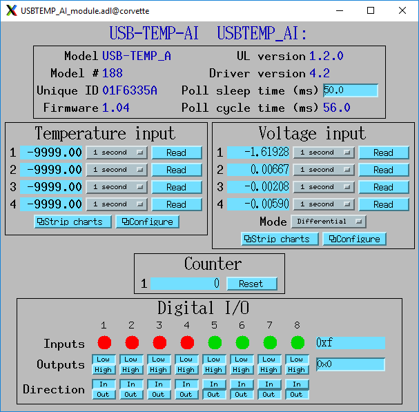
USBTEMP_AI_module.adl
The following is the screen for configuring the temperature inputs.
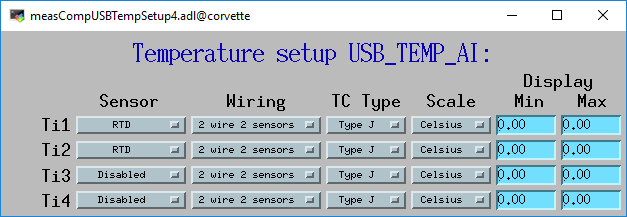
measCompUSBTempSetup4.adl
USB-1208LS
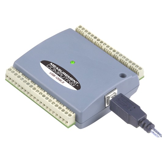
Photo of USB-1208LS
This module costs $129 and has the following features:
12-bit analog inputs
4 differential channels
Programmable per-channel range: 8 ranges from +-1V to +-20V
50 Hz maximum sampling rate. The module has a trigger input that allows higher sampling rates, but this is not yet supported in the EPICS driver.
10-bit analog outputs
2 channels, fixed 0 to +5V range
100 Hz maximum input rate
Digital inputs/outputs
16 signals, programmable as inputs or outputs in groups of 8
Counters
1 input
1 MHz maximum rate, 32-bit register
More information can be found in the USB-1208LS product description.
The USB-1208HS , USB-1208FS-Plus and USB-231 are similar devices but with higher performance. These are also supported.
The following is the main medm screen for controlling the USB-1208LS.
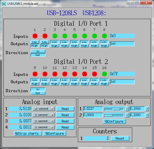
USB1208LS_module.adl
E-DIO24
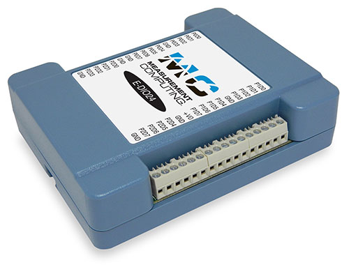
Photo of E-DIO24
This module costs $320 and has the following features:
Digital inputs/outputs
24 signals, individually programmable as inputs or outputs
Counters
1 input
10 MHz maximum rate, 32-bit register
More information can be found in the E-DIO24 product description.
The following is the main medm screen for controlling the E-DIO24.
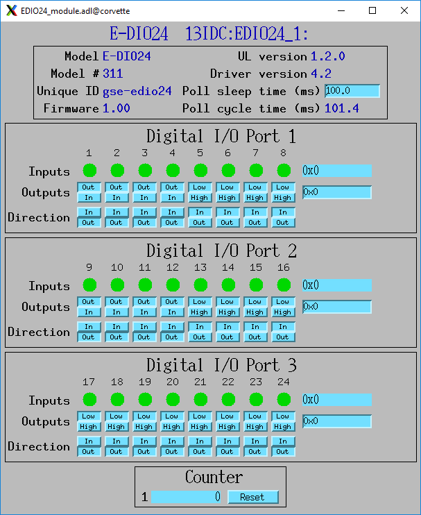
EDIO24_module.adl
USB-ERB24
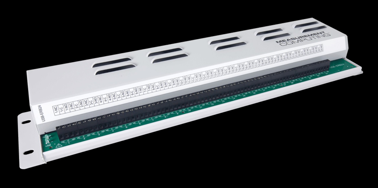
Photo of USB-ERB24
This module costs $325 and has the following features:
Relay outputs
24 Form C SPDT relay outputs, up to 6 amps at 240 VAC/28 VDC. Screw terminals with normally-open and normally closed connections for each relay.
More information can be found in the USB-ERB24 product description.
The following is the main medm screen for controlling the USB-ERB24.
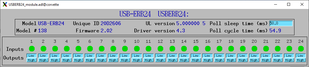
USBERB24_module.adl
USB-3100
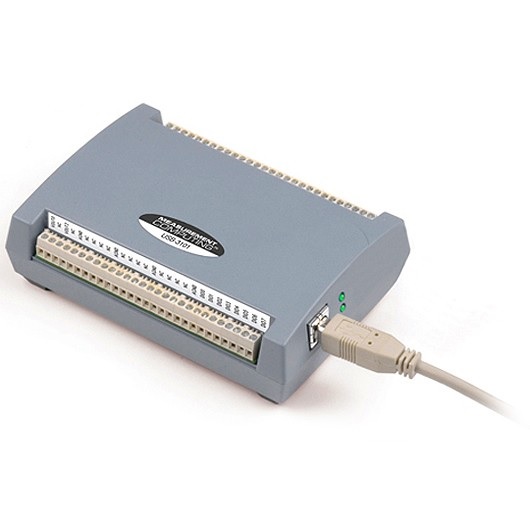
Photo of USB-3101
This series of module costs from $330 (USB-3101) to $660 (USB-3106) depending on the number of channels and the output type, and has the following features:
16-bit analog outputs
4, 8 or 16 channels, individually programmable range 0-10V or +-10V.
Some models provide 0-20 mA current output as well as voltage output
Some models have high-drive voltage output (+-40 mA)
Support for synchronously updating all DAC channels at the same time. This can be done in master or slave mode, which controls whether the SYNCLD signal is an output (master) or an input (slave).
100 Hz maximum output rate
Digital inputs/outputs
8 signals, individually programmable as inputs or outputs
Counters
1 input
1 MHz maximum rate, 32-bit register
More information can be found in the USB-3100 series product description.
The following is the main medm screen for controlling the USB-3104 8-channel unit.
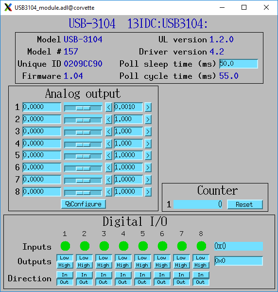
USB3104_module.adl
The following is the medm screen for configuring the analog outputs on the USB-3104 8-channel unit.
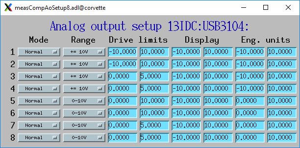
USB3104_setup.adl
Configuration
The following lines are needed in the EPICS startup script for the multifunction driver.
## Configure port driver
# MultiFunctionConfig(portName,        # The name to give to this asyn port driver
#                     uniqueID,        # For USB the serial number.  For Ethernet the MAC address or IP address.
#                     maxInputPoints,  # Maximum number of input points for waveform digitizer
#                     maxOutputPoints) # Maximum number of output points for waveform generator
MultiFunctionConfig("1608G_1", 1, 1048576, 1048576)
dbLoadTemplate("1608G.substitutions.big")
The uniqueID is a string that identifies the device to be controlled.
For USB devices the uniqueID is the serial number, which is printed on the device (e.g. “01F6335A”).
For Ethernet devices the uniqueID can either be the MAC address (e.g. “00:80:2F:24:53:DE”), or the IP address (e.g. “10.54.160.63”, or the IP DNS name (e.g. “gse-e1601-1”). The MAC address, IP address or IP name can be used for devices on the local subnet, while the IP address or IP name must be used for devices on other subnets.
The measComp module comes with example iocBoot/ directories that contain example startup scripts and example substitutions files for each supported model.
Databases
The following tables list the database template files that are used with the multi-function modules.
Overall Device Functions
These are the records defined in measCompDevice.template. This database is loaded once for each module.
EPICS record name |
EPICS record type |
asyn interface |
drvInfo string |
Description |
|---|---|---|---|---|
$(P)ModelName |
stringin |
asynOctetRead |
MODEL_NAME |
The model name of this device, e.g. “USB-1808X”. |
$(P)ModelNumber |
longin |
asynInt32 |
MODEL_NUMBER |
The model number of this device, e.g. 318. |
$(P)FirmwareVersion |
stringin |
asynOctetRead |
FIRMWARE_VERSION |
The firmware version, e.g. “1.03”. |
$(P)UniqueID |
stringin |
asynOctetRead |
UNIQUE_ID |
The unique ID of this device, e.g. “02151405” |
$(P)ULVersion |
stringin |
asynOctetRead |
UL_VERSION |
The version of the UL library on Linux or Windows, e.g. “1.2.0”. |
$(P)DriverVersion |
stringin |
asynOctetRead |
DRIVER_VERSION |
The version of the EPICS driver, e.g. “4.3”. |
$(P)PollTimeMS |
ai |
asynFloat64 |
POLL_TIME_MS |
The actual time for the last poll cycle in ms. |
$(P)PollSleepMS |
ao |
asynFloat64 |
POLL_SLEEP_MS |
The time to sleep at the end of each poll cycle in ms. |
$(P)LastErrorMessage |
waveform |
asynOctetRead |
LAST_ERROR_MESSAGE |
The last error message from the driver. |
The medm sub-screen that displays these records. The main screen for every module contains a subscreen like this.
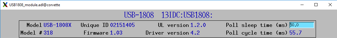
measCompDevice.adl
Analog I/O Functions
These are the records defined in measCompAnalogIn.template. This database is loaded once for each analog input channel
EPICS record name |
EPICS record type |
asyn interface |
drvInfo string |
Description |
|---|---|---|---|---|
$(P)$(R) |
ai |
asynInt32 |
ANALOG_IN_VALUE |
Analog input value. This is converted from the 16-bit unsigned integer device units from the driver to engineering units using the EGUL and EGUF fields. This value is polled in the driver at the polling frequency set by PollSleepMS. The asynInt32Average device support is used, so that the ai value is the average of all the readings from the poller since the last time the record processed. For example, if the poller is running at 100 Hz and the ai record SCAN field is “0.2 seconds” then 20 values will be averaged each time the record processes. If SCAN=I/O Intr then the device support will average the number of values specified in the SVAL field of the record. If SVAL<=1 then the record will processes on each callback, so there is no averaging. |
$(P)$(R)Range |
mbbo |
asynInt32 |
ANALOG_IN_RANGE |
Input range for this analog input channel. Choices are determined at run time based on the model in use. |
$(P)$(R)Type |
mbbo |
asynInt32 |
ANALOG_IN_TYPE |
Input type (e.g. “Volts”, “TC deg”, etc.) for this analog input channel. Choices are determined at run time based on the model in use. |
The following is the medm screen for controlling the analog input records for the USB-1608GX-2AO. Note that the engineering units limits (EGUL and EGUF) do not have to be in volts, they can be in any units such as “percent”, “degrees”, etc.
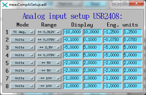
measCompAiSetup.adl
These are the records defined in measCompAnalogOut.template. This database is loaded once for each analog output channel
EPICS record name |
EPICS record type |
asyn interface |
drvInfo string |
Description |
|---|---|---|---|---|
$(P)$(R) |
ai |
asynInt32 |
ANALOG_OUT_VALUE |
Analog output value. This is converted from engineering units to the 16-bit unsigned integer device units for the driver using the EGUL and EGUF fields. |
$(P)$(R)Range |
mbbo |
asynInt32 |
ANALOG_OUT_RANGE |
Output range for this analog output channel. Choices are determined at run time based on the model in use. |
$(P)$(R)SyncMaster |
bo |
asynInt32 |
ANALOG_OUT_SYNC_MASTER |
Controls whether the SYNCLD signal is an output (0, Master) or input (1, Slave). |
$(P)$(R)SyncEnable |
bo |
asynInt32 |
ANALOG_OUT_SYNC_ENABLE |
Controls whether the analog outputs are updated synchronously.
|
$(P)$(R)SyncWrite |
bo |
asynInt32 |
ANALOG_OUT_SYNC_WRITE |
Writing to this record simultaneously updates all of the analog outputs to the values in the ao records. |
$(P)$(R)Return |
ai |
asynInt32 |
ANALOG_OUT_VALUE |
Analog output value to return to at the end of a pulse. This is converted from engineering units to the 16-bit unsigned integer device units for the driver using the EGUL and EGUF fields. |
$(P)$(R)Pulse |
bo |
N.A. |
N.A. |
Choices are “Normal” and “Pulse”. In Normal mode the Return record is ignored. In Pulse mode the $(P)($R) output is written to to hardware, followed immediately by writing the $(P)$(R)Return value. |
$(P)$(R)TweakVal |
ao |
N.A. |
N.A. |
The amount by which to tweak the out when the Tweak record is processed. |
$(P)$(R)TweakUp |
calcout |
N.A. |
N.A. |
Tweaks the output up by TweakVal. |
$(P)$(R)TweakDown |
calcout |
N.A. |
N.A. |
Tweaks the output down by TweakVal. |
NOTE for Sync records: The sync features are only supported on the USB-31xx models. The Sync records exist for all analog output channels. However, only the records for the first channel, $(P)$(R)1Sync*, are used. The screen shot for the USB-3104 above shows the sync record widgets.
The following is the medm screen for controlling the analog output records for the USB-1608GX-2AO. Note that the engineering units limits (EGUL and EGUF) do not have to be in volts, they can be in any units such as “percent”, “degrees”, etc. The drive limits can be more restrictive than the full +-10V output range of the analog outputs.
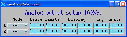
measCompAoSetup.adl
Temperature Functions
These are the records defined in measCompTemperatureIn.template. This database is loaded once for each temperature input channel.
EPICS record name |
EPICS record type |
asyn interface |
drvInfo string |
Description |
|---|---|---|---|---|
$(P)$(R) |
ai |
asynFloat64 |
TEMPERATURE_IN_VALUE |
Temperature input value. This field should be periodically scanned, since it is not currently polled in the driver, so I/O Intr scanning cannot be used. |
$(P)$(R)Scale |
mbbo |
asynInt32 |
TEMPERATURE_SCALE |
Temperature scale (units) for this temperature input channel. Choices are “Celsius” (0), “Fahrenheit” (1), “Kelvin” (2), “Volts” (4), and “Noscale” (5). |
$(P)$(R)TCType |
mbbo |
asynInt32 |
THERMOCOUPLE_TYPE |
Thermocouple type. Choices are “Type J” (1), “Type K” (2), “Type T” (3), “Type 4” (4), “Type R” (5), “Type S” (6), “Type B” (7), “Type N” (8) |
$(P)$(R)Filter |
mbbo |
asynInt32 |
TEMPERATURE_FILTER |
Temperature filter. Choices are “Filter” (0) and “No filter” (0x400) |
The following is the main medm screen for configuring the analog/temperature inputs on the USB-2408-2AO.
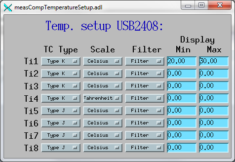
measCompTemperatureSetup.adl
Digital I/O Functions
These are the records defined in the following files:
measCompBinaryIn.template. This database is loaded once for each binary I/O bit.
measCompLongIn.template. This database is loaded once for each binary I/O register.
measCompBinaryOut.template. This database is loaded once for each binary I/O bit.
measCompLongOut.template. This database is loaded once for each binary I/O register.
measCompBinaryDir.template. This database is loaded once for each binary I/O bit.
EPICS record name |
EPICS record type |
asyn interface |
drvInfo string |
Description |
|---|---|---|---|---|
$(P)$(R) |
bi |
asynUInt32Digital |
DIGITAL_INPUT |
Digital input value. The MASK parameter in the INP link defines which bit is used. The binary inputs are polled by the driver poller thread, so these records should have SCAN=”I/O Intr”. |
$(P)$(R) |
longin |
asynUInt32Digital |
DIGITAL_INPUT |
Digital input value as a word, rather than individual bits. The MASK parameter in the INP link defines which bits are used. The binary inputs are polled by the driver poller thread, so this record should have SCAN=”I/O Intr”. |
$(P)$(R) |
bo |
asynUInt32Digital |
DIGITAL_OUTPUT |
Digital output value. The MASK parameter in the INP link defines which bit is used. |
$(P)$(R)_RBV |
bi |
asynUInt32Digital |
DIGITAL_OUTPUT |
Digital output value readback. The MASK parameter in the INP link defines which bit is used. |
$(P)$(R) |
longout |
asynUInt32Digital |
DIGITAL_OUTPUT |
Digital output value as a word, rather than individual bits. The MASK parameter in the INP link defines which bits are used. |
$(P)$(R)_RBV |
longin |
asynUInt32Digital |
DIGITAL_OUTPUT |
Digital output value readback as a word, rather than individual bits. The MASK parameter in the INP link defines which bits are used. |
$(P)$(R) |
bo |
asynUInt32Digital |
DIGITAL_DIRECTION |
Direction of this I/O line, “In” (0) or “Out” (1). The MASK parameter in the INP link defines which bit is used. |
Pulse Generator Functions
Note: These are called “timers” in Measurement Computing’s documentation.
These are the records defined in measCompPulseGen.template. This database is loaded once for each pulse generator.
EPICS record name |
EPICS record type |
asyn interface |
drvInfo string |
Description |
|---|---|---|---|---|
$(P)$(R)Run |
bo |
asynUInt32 |
PULSE_RUN |
“Run” (1) starts the pulse generator, “Stop” (0) stops the pulse generator. Note that ideally this record should go back to 0 when the pulse generator is done, if it is outputting a finite number of pulses (see Count record). But unfortunately the Measurement Computing library does not have a way to query the status of the timer to see if it is done, so this is not possible. |
$(P)$(R)Period |
ao |
asynFloat64 |
PULSE_PERIOD |
Pulse period, in seconds. The time between pulses can be defined either with the Period or with the Frequency; whenever one record is changed the other is updated with the new calculated value. |
$(P)$(R)Frequency |
ao |
N.A. |
N.A. |
Pulse frequency, in seconds. The Frequency calculates a new value of the Period, and sends the period value to the driver. |
$(P)$(R)Width |
ao |
asynFloat64 |
PULSE_WIDTH |
Pulse width, in seconds. The allowed range is 15.625 ns to (Period-15.625 ns). |
$(P)$(R)Delay |
ao |
asynFloat64 |
PULSE_DELAY |
Initial pulse delay in seconds after Run is set to 1. |
$(P)$(R)Count |
longout |
asynInt32 |
PULSE_COUNT |
Number of pulses to output. If the Count is 0 then the pulse generator runs continuously until Run is set to 0. |
$(P)$(R)IdleState |
bo |
asynInt32 |
PULSE_IDLE_STATE |
The idle state of the pulse output line, “Low” (0) or “High” (1). This determines the polarity of the pulse, i.e. positive going or negative going. |
Waveform Digitizer Functions
These records are defined in the following files:
measCompWaveformDig.template. This database is loaded once per module.
measCompWaveformDigN.template. This database is loaded for each digitizer input channel.
EPICS record name |
EPICS record type |
asyn interface |
drvInfo string |
Description |
|---|---|---|---|---|
$(P)$(R)NumPoints |
longout |
asynInt32 |
WAVEDIG_NUM_POINTS |
Number of points to digitize. This cannot be more than the value of maxInputPoints that was specified in USB1608GConfig. |
$(P)$(R)FirstChan |
mbbo |
asynInt32 |
WAVEDIG_FIRST_CHAN |
First channel to digitize. “1” (0) to “8” (7). The database currently assumes differential inputs, so only 8 inputs are available, though this can easily be extended to 16. |
$(P)$(R)NumChans |
mbbo |
asynInt32 |
WAVEDIG_NUM_CHANS |
Number of channels to digitize. “1” (0) to “8” (7). The maximum valid number is 8-FirstChan+1. The database currently assumes differential inputs, so only 8 inputs are available, though this can easily be extended to 16. |
$(P)$(R)TimeWF |
waveform |
asynFloat32Array |
WAVEDIG_TIME_WF |
Timebase waveform. These values are calculated when Dwell or NumPoints are changed. It is typically used as the X-axis in plots. |
$(P)$(R)CurrentPoint |
longin |
asynInt32 |
WAVEDIG_CURRENT_POINT |
The current point being collected. This does not always increment by 1 because the device can transfer data in blocks. |
$(P)$(R)Dwell |
ao |
asynFloat64 |
WAVEDIG_DWELL |
The time per point in seconds. The minimum time is 2 microseconds times NumChans. |
$(P)$(R)TotalTime |
ai |
asynFloat64 |
WAVEDIG_TOTAL_TIME |
The total time to digitize NumChans*NumPoints. |
$(P)$(R)ExtTrigger |
bo |
asynInt32 |
WAVEDIG_EXT_TRIGGER |
The trigger source, “Internal” (0) or “External” (1). |
$(P)$(R)ExtClock |
bo |
asynInt32 |
WAVEDIG_EXT_CLOCK |
The clock source, “Internal” (0) or “External” (1). If External is used then the Dwell record does not control the digitization rate, it is controlled by the external clock. However Dwell should be set to approximately the correct value if possible, because that controls what type of data transfers the device uses. |
$(P)$(R)Continuous |
bo |
asynInt32 |
WAVEDIG_CONTINUOUS |
Values are “One-shot” (0) or “Continuous” (1). This controls whether the device stops when acquisition is complete, or immediately begins another acquisition. Typically “One-shot” is used, because the driver is currently not double-buffered, so data could be overwritten before the driver has a chance to read the data. One exception is when using Retrigger=Enable and TriggerCount less than NumPoints. In that case each trigger will only collect TriggerCount samples, and one wants to use Continuous so that it collects the next TriggerCount samples on the next trigger input. |
$(P)$(R)AutoRestart |
bo |
asynInt32 |
WAVEDIG_AUTO_RESTART |
Values are “Disable” (0) and “Enable” (1). This controls whether the driver automatically starts another acquire when the previous one completes. This is different from Continuous mode described above, because this is a software restart that only happens after the driver has read the buffer from the previous acquisition. |
$(P)$(R)Retrigger |
bo |
asynInt32 |
WAVEDIG_RETRIGGER |
Values are “Disable” (0) and “Enable” (1). This controls whether the device rearms the trigger input after a trigger is received. |
$(P)$(R)TriggerCount |
longout |
asynInt32 |
WAVEDIG_TRIGGER_COUNT |
This controls how many samples are collected on each trigger input. 0 means collect NumPoint samples. If TriggerCount is less than NumPoints, Retrigger=Enable and Continuous=Enable then each time a trigger is received TriggerCount samples will be collected. |
$(P)$(R)BurstMode |
bo |
asynInt32 |
WAVEDIG_BURST_MODE |
Values are “Disable” (0) and “Enable” (1). This controls whether the device digitizes all NumChans channels as quickly as possible during each sample, or whether it digitizes successive channels at evenly spaced time intevals during the Dwell time. Enabling BurstMode means that all channels are digitized 2 microseconds apart. This can reduce the accuracy if the channels have very different voltages because of the settling time and slew rate limitations of the system. |
$(P)$(R)Run |
busy |
asynInt32 |
WAVEDIG_RUN |
Values are “Stop” (0) and “Run” (1). This starts and stops the waveform digitizer. |
$(P)$(R)ReadWF |
busy |
asynInt32 |
WAVEDIG_READ_WF |
Values are “Done” (0) and “Read” (1). This reads the waveform data from the device buffers into the waveform records. Note that the driver always reads device when acquisition stops, so for quick acquisitions this record can be Passive. To see partial data during long acquisitions this record can be periodically processed. |
$(P)$(R)VoltWF |
waveform |
asynFloat64Array |
WAVEDIG_VOLT_WF |
This waveform record contains the digitizer waveform data for channel N. This record has scan=I/O Intr, and it will process whenever acquisition completes, or whenever the ReadWF record above processes. The data are in volts. |
This is a plot of a digitized waveform captured of someone speaking into a microphone.
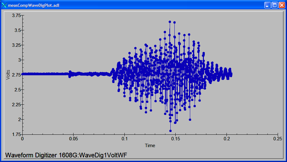
Waveform digitizer plot
Waveform Generator Functions
These records are defined in the following files:
measCompWaveformGen.template. This database is loaded once per module.
measCompWaveformGenN.template. This database is loaded for each waveform generator output channel.
EPICS record name |
EPICS record type |
asyn interface |
drvInfo string |
Description |
|---|---|---|---|---|
$(P)$(R)NumPoints |
longin |
asynInt32 |
WAVEGEN_NUM_POINTS |
Number of points output waveform. The value of this record is equal to UserNumPoints if user-defined waveforms are selected, or IntNumPoints if internal predefined waveforms are selected. |
$(P)$(R)UserNumPoints |
longout |
asynInt32 |
WAVEGEN_USER_NUM_POINTS |
Number of points in user-defined output waveforms. This cannot be more than the value of maxOutputPoints that was specified in USB1608GConfig. |
$(P)$(R)IntNumPoints |
longout |
asynInt32 |
WAVEGEN_INT_NUM_POINTS |
Number of points in internal predefined output waveforms. This cannot be more than the value of maxOutputPoints that was specified in USB1608GConfig. |
$(P)$(R)UserTimeWF |
waveform |
asynFloat32Array |
WAVEDIG_USER_TIME_WF |
Timebase waveform for user-defined waveforms. These values are calculated when UserDwell or UserNumPoints are changed. It is typically used as the X-axis in plots. |
$(P)$(R)IntTimeWF |
waveform |
asynFloat32Array |
WAVEGEN_INT_TIME_WF |
Timebase waveform for internal predefined waveforms. These values are calculated when IntDwell or IntNumPoints are changed. It is typically used as the X-axis in plots. |
$(P)$(R)CurrentPoint |
longin |
asynInt32 |
WAVEGEN_CURRENT_POINT |
The current point being output. This does not always increment by 1 because the device can transfer data in blocks. |
$(P)$(R)Frequency |
ai |
asynFloat64 |
WAVEGEN_FREQUENCY |
The output frequency (waveforms/second). The value of this record is equal to UserFrequency if user-defined waveforms are selected, or IntFrequency if internal predefined waveforms are selected. |
$(P)$(R)Dwell |
ai |
asynFloat64 |
WAVEGEN_DWELL |
The output dwell time or period (seconds/sample). The value of this record is equal to UserDwell if user-defined waveforms are selected, or IntDwell if internal predefined waveforms are selected. |
$(P)$(R)UserDwell |
ao |
asynFloat64 |
WAVEGEN_USER_DWELL |
The output dwell time or period (seconds/sample) for user-defined waveforms. This record is automatically changed if UserFrequency is modified. |
$(P)$(R)IntDwell |
ao |
asynFloat64 |
WAVEGEN_INT_DWELL |
The output dwell time or period (seconds/sample) for internal predefined waveforms. This record is automatically changed if IntFrequency is modified. |
$(P)$(R)UserFrequency |
ao |
N.A. |
N.A. |
The output frequency (waveforms/second) for user-defined waveforms. This record computes UserDwell and writes to that record. This record is automatically changed if UserDwell is modified. |
$(P)$(R)IntFrequency |
ao |
N.A. |
N.A. |
The output frequency (waveforms/second) for internal predefined waveforms. This record computes IntDwell and writes to that record. This record is automatically changed if IntDwell is modified. |
$(P)$(R)TotalTime |
ai |
asynFloat64 |
WAVEGEN_TOTAL_TIME |
The total time to output the waveforms. This is Dwell*NumPoints. |
$(P)$(R)ExtTrigger |
bo |
asynInt32 |
WAVEGEN_EXT_TRIGGER |
The trigger source, “Internal” (0) or “External” (1). |
$(P)$(R)ExtClock |
bo |
asynInt32 |
WAVEGEN_EXT_CLOCK |
The clock source, “Internal” (0) or “External” (1). If External is used then the Dwell record does not control the output rate, it is controlled by the external clock. However Dwell should be set to approximately the correct value if possible, because that controls what type of data transfers the device uses. |
$(P)$(R)Continuous |
bo |
asynInt32 |
WAVEGEN_CONTINUOUS |
Values are “One-shot” (0) or “Continuous” (1). This controls whether the device stops when the output waveform is complete, or immediately begins again at the start of the waveform. |
$(P)$(R)Retrigger |
bo |
asynInt32 |
WAVEGEN_RETRIGGER |
Values are “Disable” (0) and “Enable” (1). This controls whether the device rearms the trigger input after a trigger is received. |
$(P)$(R)TriggerCount |
longout |
asynInt32 |
WAVEGEN_TRIGGER_COUNT |
This controls how many values are output on each trigger input. 0 means output NumPoints samples. If TriggerCount is less than NumPoints, Retrigger=Enable and Continuous=Enable then each time a trigger is received TriggerCount samples will be output. |
$(P)$(R)Run |
busy |
asynInt32 |
WAVEGEN_RUN |
Values are “Stop” (0) and “Run” (1). This starts and stops the waveform generator. |
$(P)$(R)UserWF |
waveform |
asynFloat32Array |
WAVEGEN_USER_WF |
This waveform record contains the user-defined waveform generator data for channel N. The data are in volts. These data are typically generated by an EPICS Channel Access client. |
$(P)$(R)InternalWF |
waveform |
asynFloat32Array |
WAVEGEN_INT_WF |
This waveform record contains the internal predefined waveform generator data for channel N. The data are in volts. |
$(P)$(R)Enable |
bo |
asynInt32 |
WAVEGEN_ENABLE |
Values are “Disable” and “Enable”. Controls whether channel N output is enabled. |
$(P)$(R)Type |
mbbo |
asynInt32 |
WAVEGEN_WAVE_TYPE |
Controls the waveform type on channel N. Values are “User-defined” and “Sin wave”, “Square wave”, “Sawtooth”, “Pulse”, or “Random”. Note that if any channel is “User-defined” then all channels must be. Note that all internally predefined waveforms are symmetric about 0 volts. To output unipolar signals the Offset should be set to +-Amplitude/2. |
$(P)$(R)PulseWidth |
ao |
asynFloat64 |
WAVEGEN_PULSE_WIDTH |
Controls the pulse width in seconds if Type is “Pulse”. |
$(P)$(R)PulseDelay |
ao |
asynFloat64 |
WAVEGEN_PULSE_DELAY |
Controls the time of the beginning of the pulse relative to the start of the waveform if Type is “Pulse”. This is useful when multiple waveforms are output, and one wants to control the relative time offset. |
$(P)$(R)Amplitude |
ao |
asynFloat64 |
WAVEGEN_AMPLITUDE |
Controls the amplitude of the waveform. For internally predefined waveforms this directly controls the peak-to-peak amplitude in volts. For user-defined waveforms this is a scale factor that multiplies the values in the waveform, i.e. 1.0 outputs the user-defined waveform unchanged, 2.0 increases the amplitide by 2, etc. For both internal and used-defined waveforms changing the sign of the Amplitude controls the polarity of the signal. |
$(P)$(R)Offset |
ao |
asynFloat64 |
WAVEGEN_OFFSET |
Controls the offset of the waveform in volts. For user-defined waveforms, this value is added to the waveform, i.e. 0.0 outputs the user-defined waveform unchanged, 1.0 adds 1 volt, etc. For internally defined waveforms all types except Pulse are centered at 0V if Offset=0, e.g. Sin wave goes from +Amplitude to -Amplitude. If Offset is non-zero it is added to this waveform. If waveform Type=Pulse it is not centered on 0V. The baseline=Offset, and the pulse height is Amplitude relative to the baseline. This was a change made in R4-3. |
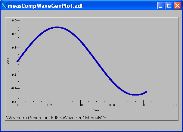
Plot of an internal predefined waveform (sin wave)
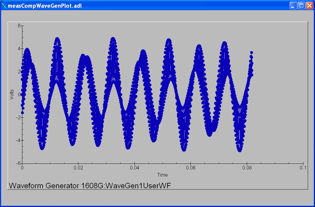
Plot of a user-defined waveform (sum of sin and cos waves)
Trigger Functions
These records are defined in measCompTrigger.template. This database is loaded once per module.
EPICS record name |
EPICS record type |
asyn interface |
drvInfo string |
Description |
|---|---|---|---|---|
$(P)$(R)Mode |
mbbo |
asynInt32 |
TRIGGER_MODE |
The mode of the external trigger input. Choices are “Positive edge”, “Negative edge”, “High”, and “Low”. |
Box for USB-CTR08, USB-3104, and USB-1808X
The following photo is a box we built to house the USB-CTR08, USB-3104, and USB-1808X and provide BNC I/O connections.
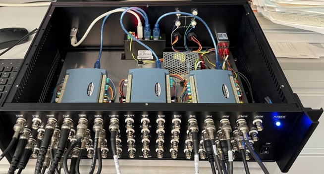
GSECARS designed box for USB-CTR08, USB-3104, and USB-1808X
Box for USB-2408-2AO
The following photos show a box we built to house the USB-2408-2AO and provide I/O connections.
This is the top view.
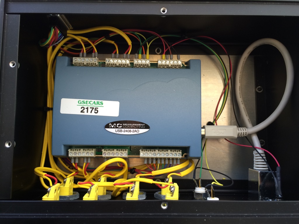
Top view of USB-2408-2AO box
These are the side views.
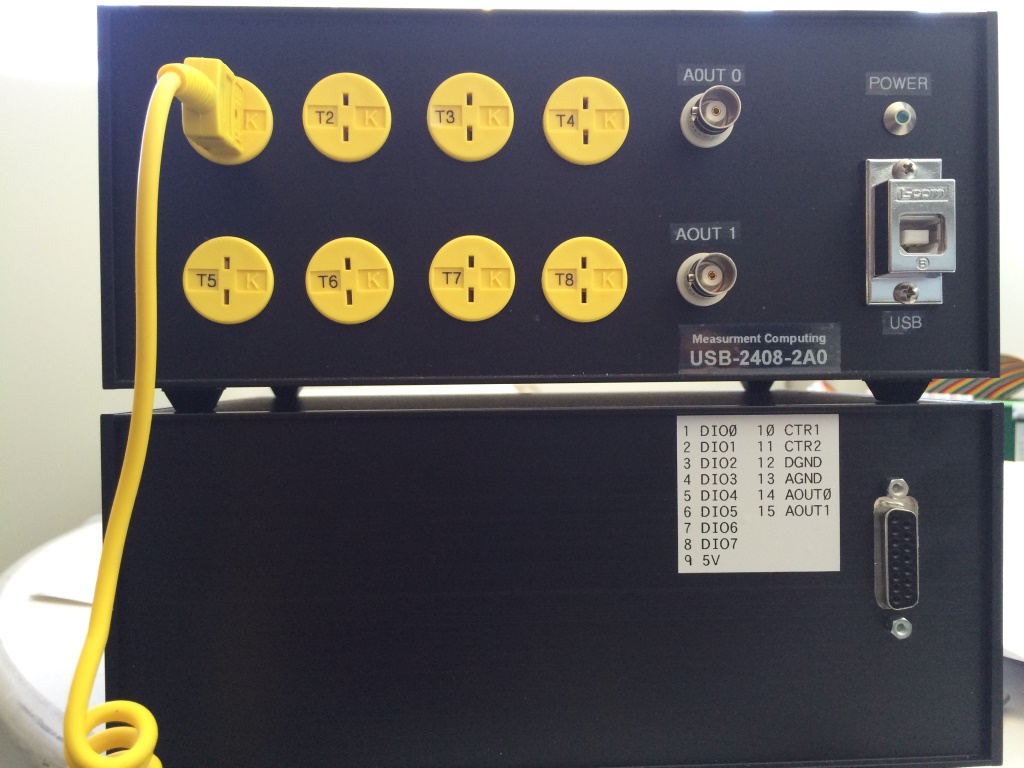
Side views of USB-2408-2AO box
Performance measurements
The following summarizes a simple test of the precision and accuracy of the analog outputs and analog inputs of the USB-1608GX-2AO. The test configuration was with Analog Output 0 connected to Analog Input 0, and also to a Keithley 2700 digital multimeter. The Keithley is a 6.5 digit (22 bit) device, so it can be used to measure the accuracy of the USB-1608GX-2AO analog output, and provide the “true” value to measure the accuracy of the analog input. The 1608GX analog inputs records and the Keithley input had SCAN=0.1 second, so new readings were being made at 10Hz. The following IDL test program was used to drive the analog output from -10V to +10V in 0.1V steps. 10 readings were made of the 1608GX analog inputs, and one reading of the Keithley at each voltage step. These tests were done with the +-10V range of the analog outputs and analog inputs. Since these are 16-bit devices, one bit is 20V/65536 = 0.000305 volts.
pro test_analog_performance_1608,  ao=ao, ai=ai, min_volts=min_volts, max_volts=max_volts, $
                                   step_volts=step_volts, num_samples=num_samples, delay=delay, $
                                   keithley=keithley, results

  if (n_elements(ao)          eq 0) then ao          = '1608G:Ao1'
  if (n_elements(ai)          eq 0) then ai          = '1608G:Ai1'
  if (n_elements(min_volts)   eq 0) then min_volts   = -10.0
  if (n_elements(max_volts)   eq 0) then max_volts   =  10.0
  if (n_elements(step_volts)  eq 0) then step_volts  = 0.1
  if (n_elements(num_samples) eq 0) then num_samples = 10
  if (n_elements(delay)       eq 0) then delay       = 0.1
  if (n_elements(keithley)    eq 0) then keithley    = '13LAB:DMM2Dmm_raw.VAL'

  output = min_volts
  samples = dblarr(num_samples)
  num_points = ((max_volts - min_volts) / step_volts + 0.5) + 1
  results = dblarr(4, num_points)
  for i=0, num_points-1 do begin
    output = min_volts + i*step_volts
    t = caput(ao, output)
    wait, 2*delay
    for j=0, num_samples-1 do begin
      wait, delay
      t = caget(ai, temp)
      samples[j] = temp
    endfor
    m = moment(samples)
    results[0,i] = output
    results[1,i] = m[0]
    results[2,i] = sqrt(m[1])
    t = caget(keithley, temp)
    results[3,i] = temp
    print, results[0,i], results[1,i], results[2,i], results[3,i]
  endfor
end
The following plot shows the difference of the nominal USB-1608GX-2AO analog output voltage from the Keithley 2700 reading. The mean error is 0.000312V, or just over 1 bit. The RMS error is 0.000203V, or less than 1 bit.
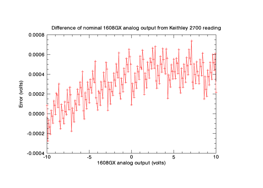
USB-1608GX-2AO analog output voltage error
The following plot shows the difference of the mean of 10 readings of the 1608GX analog input voltage from the Keithley 2700 reading. The mean error is 0.000106V, less than 1 bit. The RMS error is 0.000259V, also less than 1 bit.
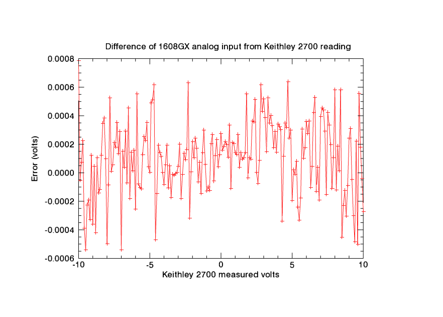
USB-1608GX-2AO analog input voltage error
The following plot shows the standard deviation of 10 readings of the 1608GX analog input voltage. The values range from about 0.001V (~3 bits) at +-10V to less than 0.0003V (1 bit) between -2 and +2V.
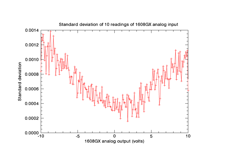
USB-1608GX-2AO analog input standard deviation
The following table contains all of the results from the tests.
1608GX analog output (nominal) |
1608GX analog input (mean of 10 readings) |
Std. Dev. of 10 1608GX analog input readings |
Keithley 2700 reading |
|---|---|---|---|
-10.00000 |
-9.99930 |
0.00084 |
-10.00008 |
-9.90000 |
-9.89978 |
0.00130 |
-9.89972 |
-9.80000 |
-9.79986 |
0.00126 |
-9.79994 |
-9.70000 |
-9.69964 |
0.00134 |
-9.69987 |
-9.60000 |
-9.60018 |
0.00123 |
-9.59979 |
-9.50000 |
-9.50057 |
0.00099 |
-9.50003 |
-9.40000 |
-9.40020 |
0.00117 |
-9.39997 |
-9.30000 |
-9.30010 |
0.00080 |
-9.29991 |
-9.20000 |
-9.20046 |
0.00105 |
-9.20013 |
-9.10000 |
-9.09996 |
0.00118 |
-9.10009 |
-9.00000 |
-9.00035 |
0.00122 |
-8.99999 |
-8.90000 |
-8.90016 |
0.00079 |
-8.90021 |
-8.80000 |
-8.80061 |
0.00118 |
-8.80019 |
-8.70000 |
-8.69996 |
0.00138 |
-8.70007 |
-8.60000 |
-8.60044 |
0.00112 |
-8.60030 |
-8.50000 |
-8.50004 |
0.00098 |
-8.49992 |
-8.40000 |
-8.39973 |
0.00103 |
-8.39985 |
-8.30000 |
-8.29975 |
0.00132 |
-8.30009 |
-8.20000 |
-8.19965 |
0.00108 |
-8.20003 |
-8.10000 |
-8.09986 |
0.00115 |
-8.09995 |
-8.00000 |
-8.00040 |
0.00079 |
-7.99990 |
-7.90000 |
-7.90021 |
0.00088 |
-7.90012 |
-7.80000 |
-7.79950 |
0.00107 |
-7.80002 |
-7.70000 |
-7.69998 |
0.00099 |
-7.69999 |
-7.60000 |
-7.60018 |
0.00092 |
-7.60024 |
-7.50000 |
-7.49990 |
0.00080 |
-7.50011 |
-7.40000 |
-7.39986 |
0.00097 |
-7.40004 |
-7.30000 |
-7.29992 |
0.00101 |
-7.30027 |
-7.20000 |
-7.20006 |
0.00085 |
-7.20019 |
-7.10000 |
-7.09953 |
0.00100 |
-7.09982 |
-7.00000 |
-7.00060 |
0.00088 |
-7.00006 |
-6.90000 |
-6.89986 |
0.00097 |
-6.90001 |
-6.80000 |
-6.79988 |
0.00089 |
-6.79992 |
-6.70000 |
-6.69984 |
0.00107 |
-6.70013 |
-6.60000 |
-6.60017 |
0.00091 |
-6.60010 |
-6.50000 |
-6.49958 |
0.00088 |
-6.50003 |
-6.40000 |
-6.40043 |
0.00105 |
-6.40025 |
-6.30000 |
-6.30005 |
0.00088 |
-6.30020 |
-6.20000 |
-6.20008 |
0.00085 |
-6.20009 |
-6.10000 |
-6.10016 |
0.00076 |
-6.10032 |
-6.00000 |
-6.00052 |
0.00068 |
-6.00026 |
-5.90000 |
-5.89963 |
0.00077 |
-5.90018 |
-5.80000 |
-5.80050 |
0.00076 |
-5.80043 |
-5.70000 |
-5.70013 |
0.00066 |
-5.70003 |
-5.60000 |
-5.60006 |
0.00066 |
-5.59995 |
-5.50000 |
-5.50008 |
0.00082 |
-5.50021 |
-5.40000 |
-5.39989 |
0.00090 |
-5.40015 |
-5.30000 |
-5.29982 |
0.00081 |
-5.30005 |
-5.20000 |
-5.19997 |
0.00087 |
-5.20032 |
-5.10000 |
-5.10021 |
0.00048 |
-5.10025 |
-5.00000 |
-5.00011 |
0.00054 |
-5.00011 |
-4.90000 |
-4.89986 |
0.00071 |
-4.90035 |
-4.80000 |
-4.79976 |
0.00070 |
-4.80027 |
-4.70000 |
-4.69960 |
0.00082 |
-4.70021 |
-4.60000 |
-4.60090 |
0.00054 |
-4.60043 |
-4.50000 |
-4.50050 |
0.00072 |
-4.50035 |
-4.40000 |
-4.40012 |
0.00076 |
-4.40032 |
-4.30000 |
-4.30039 |
0.00045 |
-4.30053 |
-4.20000 |
-4.20005 |
0.00066 |
-4.20016 |
-4.10000 |
-4.10010 |
0.00068 |
-4.10010 |
-4.00000 |
-4.00012 |
0.00062 |
-4.00004 |
-3.90000 |
-3.90018 |
0.00060 |
-3.90023 |
-3.80000 |
-3.80002 |
0.00059 |
-3.80021 |
-3.70000 |
-3.70019 |
0.00049 |
-3.70009 |
-3.60000 |
-3.60027 |
0.00056 |
-3.60032 |
-3.50000 |
-3.50042 |
0.00063 |
-3.50025 |
-3.40000 |
-3.40017 |
0.00048 |
-3.40016 |
-3.30000 |
-3.30043 |
0.00045 |
-3.30042 |
-3.20000 |
-3.20034 |
0.00064 |
-3.20033 |
-3.10000 |
-3.10027 |
0.00066 |
-3.10027 |
-3.00000 |
-3.00047 |
0.00043 |
-3.00052 |
-2.90000 |
-2.90025 |
0.00060 |
-2.90045 |
-2.80000 |
-2.80021 |
0.00044 |
-2.80003 |
-2.70000 |
-2.70033 |
0.00038 |
-2.70032 |
-2.60000 |
-2.60011 |
0.00058 |
-2.60024 |
-2.50000 |
-2.50001 |
0.00063 |
-2.50010 |
-2.40000 |
-2.40015 |
0.00051 |
-2.40032 |
-2.30000 |
-2.29960 |
0.00043 |
-2.30023 |
-2.20000 |
-2.20050 |
0.00041 |
-2.20019 |
-2.10000 |
-2.10040 |
0.00048 |
-2.10041 |
-2.00000 |
-2.00012 |
0.00054 |
-2.00034 |
-1.90000 |
-1.90018 |
0.00044 |
-1.90028 |
-1.80000 |
-1.80026 |
0.00044 |
-1.80050 |
-1.70000 |
-1.70025 |
0.00062 |
-1.70042 |
-1.60000 |
-1.60043 |
0.00041 |
-1.60036 |
-1.50000 |
-1.50054 |
0.00044 |
-1.50061 |
-1.40000 |
-1.40035 |
0.00037 |
-1.40021 |
-1.30000 |
-1.30001 |
0.00043 |
-1.30015 |
-1.20000 |
-1.20006 |
0.00035 |
-1.20036 |
-1.10000 |
-1.10024 |
0.00048 |
-1.10029 |
-1.00000 |
-1.00035 |
0.00052 |
-1.00022 |
-0.90000 |
-0.90056 |
0.00036 |
-0.90046 |
-0.80000 |
-0.80052 |
0.00050 |
-0.80040 |
-0.70000 |
-0.70011 |
0.00041 |
-0.70032 |
-0.60000 |
-0.60029 |
0.00036 |
-0.60056 |
-0.50000 |
-0.50056 |
0.00035 |
-0.50050 |
-0.40000 |
-0.40031 |
0.00032 |
-0.40042 |
-0.30000 |
-0.30042 |
0.00030 |
-0.30065 |
-0.20000 |
-0.20053 |
0.00048 |
-0.20058 |
-0.10000 |
-0.10037 |
0.00041 |
-0.10050 |
0.00000 |
0.00018 |
0.00030 |
-0.00009 |
0.10000 |
0.09986 |
0.00046 |
0.09970 |
0.20000 |
0.19995 |
0.00032 |
0.19977 |
0.30000 |
0.30005 |
0.00035 |
0.29983 |
0.40000 |
0.39979 |
0.00046 |
0.39959 |
0.50000 |
0.49979 |
0.00032 |
0.49968 |
0.60000 |
0.60008 |
0.00028 |
0.59974 |
0.70000 |
0.69941 |
0.00041 |
0.69952 |
0.80000 |
0.79979 |
0.00019 |
0.79957 |
0.90000 |
0.89986 |
0.00037 |
0.89965 |
1.00000 |
0.99956 |
0.00032 |
0.99942 |
1.10000 |
1.09966 |
0.00051 |
1.09953 |
1.20000 |
1.19982 |
0.00045 |
1.19955 |
1.30000 |
1.29940 |
0.00041 |
1.29936 |
1.40000 |
1.39959 |
0.00041 |
1.39945 |
1.50000 |
1.49990 |
0.00035 |
1.49981 |
1.60000 |
1.59969 |
0.00035 |
1.59959 |
1.70000 |
1.69979 |
0.00052 |
1.69965 |
1.80000 |
1.80029 |
0.00016 |
1.79974 |
1.90000 |
1.89944 |
0.00050 |
1.89948 |
2.00000 |
1.99966 |
0.00047 |
1.99956 |
2.10000 |
2.09973 |
0.00045 |
2.09964 |
2.20000 |
2.19980 |
0.00041 |
2.19944 |
2.30000 |
2.29984 |
0.00044 |
2.29948 |
2.40000 |
2.40006 |
0.00023 |
2.39955 |
2.50000 |
2.49934 |
0.00032 |
2.49933 |
2.60000 |
2.59937 |
0.00038 |
2.59945 |
2.70000 |
2.69963 |
0.00054 |
2.69954 |
2.80000 |
2.79994 |
0.00032 |
2.79932 |
2.90000 |
2.90010 |
0.00033 |
2.89967 |
3.00000 |
3.00026 |
0.00021 |
2.99974 |
3.10000 |
3.09990 |
0.00027 |
3.09951 |
3.20000 |
3.19976 |
0.00041 |
3.19961 |
3.30000 |
3.30022 |
0.00022 |
3.29970 |
3.40000 |
3.39977 |
0.00061 |
3.39942 |
3.50000 |
3.49990 |
0.00045 |
3.49950 |
3.60000 |
3.59991 |
0.00068 |
3.59958 |
3.70000 |
3.69952 |
0.00039 |
3.69934 |
3.80000 |
3.79974 |
0.00052 |
3.79945 |
3.90000 |
3.89969 |
0.00043 |
3.89954 |
4.00000 |
3.99994 |
0.00029 |
3.99960 |
4.10000 |
4.09967 |
0.00042 |
4.09935 |
4.20000 |
4.19974 |
0.00063 |
4.19944 |
4.30000 |
4.29950 |
0.00058 |
4.29984 |
4.40000 |
4.39973 |
0.00066 |
4.39961 |
4.50000 |
4.50001 |
0.00055 |
4.49966 |
4.60000 |
4.60005 |
0.00048 |
4.59973 |
4.70000 |
4.70014 |
0.00043 |
4.69951 |
4.80000 |
4.79982 |
0.00059 |
4.79957 |
4.90000 |
4.89995 |
0.00069 |
4.89965 |
5.00000 |
4.99925 |
0.00059 |
4.99945 |
5.10000 |
5.09960 |
0.00066 |
5.09958 |
5.20000 |
5.19963 |
0.00087 |
5.19964 |
5.30000 |
5.29952 |
0.00072 |
5.29944 |
5.40000 |
5.39925 |
0.00084 |
5.39949 |
5.50000 |
5.49926 |
0.00059 |
5.49959 |
5.60000 |
5.59918 |
0.00065 |
5.59935 |
5.70000 |
5.70004 |
0.00073 |
5.69973 |
5.80000 |
5.79989 |
0.00081 |
5.79979 |
5.90000 |
5.89972 |
0.00087 |
5.89954 |
6.00000 |
6.00000 |
0.00076 |
5.99964 |
6.10000 |
6.10001 |
0.00038 |
6.09973 |
6.20000 |
6.19986 |
0.00047 |
6.19950 |
6.30000 |
6.29947 |
0.00071 |
6.29958 |
6.40000 |
6.39973 |
0.00077 |
6.39968 |
6.50000 |
6.49986 |
0.00068 |
6.49943 |
6.60000 |
6.60005 |
0.00091 |
6.59952 |
6.70000 |
6.69947 |
0.00085 |
6.69960 |
6.80000 |
6.79939 |
0.00065 |
6.79935 |
6.90000 |
6.89924 |
0.00083 |
6.89944 |
7.00000 |
6.99989 |
0.00074 |
6.99950 |
7.10000 |
7.09972 |
0.00091 |
7.09926 |
7.20000 |
7.20012 |
0.00074 |
7.19968 |
7.30000 |
7.30004 |
0.00073 |
7.29975 |
7.40000 |
7.39934 |
0.00061 |
7.39950 |
7.50000 |
7.50002 |
0.00073 |
7.49960 |
7.60000 |
7.60003 |
0.00074 |
7.59969 |
7.70000 |
7.69967 |
0.00101 |
7.69948 |
7.80000 |
7.79947 |
0.00089 |
7.79958 |
7.90000 |
7.89972 |
0.00094 |
7.89961 |
8.00000 |
8.00027 |
0.00083 |
7.99969 |
8.10000 |
8.09934 |
0.00090 |
8.09945 |
8.20000 |
8.19971 |
0.00095 |
8.19952 |
8.30000 |
8.29963 |
0.00112 |
8.29961 |
8.40000 |
8.39997 |
0.00073 |
8.39939 |
8.50000 |
8.49903 |
0.00089 |
8.49948 |
8.60000 |
8.59962 |
0.00080 |
8.59985 |
8.70000 |
8.69950 |
0.00109 |
8.69963 |
8.80000 |
8.79945 |
0.00084 |
8.79975 |
8.90000 |
8.89973 |
0.00111 |
8.89982 |
9.00000 |
8.99980 |
0.00083 |
8.99956 |
9.10000 |
9.09993 |
0.00071 |
9.09962 |
9.20000 |
9.19966 |
0.00098 |
9.19971 |
9.30000 |
9.29918 |
0.00090 |
9.29948 |
9.40000 |
9.39910 |
0.00097 |
9.39958 |
9.50000 |
9.49987 |
0.00106 |
9.49965 |
9.60000 |
9.59890 |
0.00102 |
9.59940 |
9.70000 |
9.70004 |
0.00110 |
9.69948 |
9.80000 |
9.79974 |
0.00105 |
9.79956 |
9.90000 |
9.89935 |
0.00112 |
9.89939 |
10.00000 |
9.99951 |
0.00058 |
9.99978 |