Driver for the USB-CTR08
- author:
Mark Rivers, University of Chicago
Introduction
This is an EPICS driver for the USB-CTR04 and USB-CTR08 counter/timer modules from MeasurementComputing.
The driver is written in C++, and consists of a class that inherits from asynPortDriver, which is part of the EPICS asyn module.
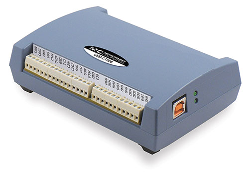
Photo of USB-CTR08
This module has the following features:
Digital inputs/outputs
8 signals, individually programmable as inputs or outputs
Pulse generators. 4 pulse generators each with
48MHz clock, 32-bit registers
Programmable period, width, number of pulses, polarity
Counters. 8 counters (USB-CTR08) or 4 counters (USB-CTR04)
48 MHz maximum count rate
Support for EPICS scaler record (similar to Joerger VSC and SIS3820)
Support for Multi-Channel Scaler (MCS) mode, similar to SIS3820.
Configuration
The following lines are needed in the EPICS startup script for the USBCTR.
# This line is for Linux only
cbAddBoard("USB-CTR", "")

## Set the minimum sleep time to 1 ms
asynSetMinTimerPeriod(0.001)

## Configure port driver
# USBCTRConfig(portName,       # The name to give to this asyn port driver
#              boardNum,       # The number of this board assigned by the Measurement Computing Instacal program
#              maxTimePoints)  # Maximum number of time points for MCS
USBCTRConfig("$(PORT)", 0, 2048, .01)

#asynSetTraceMask($(PORT), 0, TRACE_ERROR|TRACE_FLOW|TRACEIO_DRIVER)

dbLoadTemplate("USBCTR.substitutions")

# This loads the scaler record and supporting records
dbLoadRecords("$(SCALER)/db/scaler.db", "P=USBCTR:, S=scaler1, DTYP=Asyn Scaler, OUT=@asyn(USBCTR), FREQ=10000000")

# This database provides the support for the MCS functions
dbLoadRecords("$(MEASCOMP)/measCompApp/Db/measCompMCS.template", "P=$(PREFIX), PORT=$(PORT)")

# Load either MCA or waveform records below
# The number of records loaded must be the same as MAX_COUNTERS defined above

# Load the MCA records
#dbLoadRecords("$(MCA)/mcaApp/Db/simple_mca.db", "P=$(PREFIX), M=$(RNAME)1,  DTYP=asynMCA, INP=@asyn($(PORT) 0),  PREC=3, CHANS=$(MAX_POINTS)")
#dbLoadRecords("$(MCA)/mcaApp/Db/simple_mca.db", "P=$(PREFIX), M=$(RNAME)2,  DTYP=asynMCA, INP=@asyn($(PORT) 1),  PREC=3, CHANS=$(MAX_POINTS)")
#dbLoadRecords("$(MCA)/mcaApp/Db/simple_mca.db", "P=$(PREFIX), M=$(RNAME)3,  DTYP=asynMCA, INP=@asyn($(PORT) 2),  PREC=3, CHANS=$(MAX_POINTS)")
#dbLoadRecords("$(MCA)/mcaApp/Db/simple_mca.db", "P=$(PREFIX), M=$(RNAME)4,  DTYP=asynMCA, INP=@asyn($(PORT) 3),  PREC=3, CHANS=$(MAX_POINTS)")
#dbLoadRecords("$(MCA)/mcaApp/Db/simple_mca.db", "P=$(PREFIX), M=$(RNAME)5,  DTYP=asynMCA, INP=@asyn($(PORT) 4),  PREC=3, CHANS=$(MAX_POINTS)")
#dbLoadRecords("$(MCA)/mcaApp/Db/simple_mca.db", "P=$(PREFIX), M=$(RNAME)6,  DTYP=asynMCA, INP=@asyn($(PORT) 5),  PREC=3, CHANS=$(MAX_POINTS)")
#dbLoadRecords("$(MCA)/mcaApp/Db/simple_mca.db", "P=$(PREFIX), M=$(RNAME)7,  DTYP=asynMCA, INP=@asyn($(PORT) 6),  PREC=3, CHANS=$(MAX_POINTS)")
#dbLoadRecords("$(MCA)/mcaApp/Db/simple_mca.db", "P=$(PREFIX), M=$(RNAME)8,  DTYP=asynMCA, INP=@asyn($(PORT) 7),  PREC=3, CHANS=$(MAX_POINTS)")
#dbLoadRecords("$(MCA)/mcaApp/Db/simple_mca.db", "P=$(PREFIX), M=$(RNAME)9,  DTYP=asynMCA, INP=@asyn($(PORT) 8),  PREC=3, CHANS=$(MAX_POINTS)")

# This loads the waveform records
dbLoadRecords("$(MCA)/mcaApp/Db/SIS38XX_waveform.template", "P=$(PREFIX), R=$(RNAME)1,  INP=@asyn($(PORT) 0),  CHANS=$(MAX_POINTS)")
dbLoadRecords("$(MCA)/mcaApp/Db/SIS38XX_waveform.template", "P=$(PREFIX), R=$(RNAME)2,  INP=@asyn($(PORT) 1),  CHANS=$(MAX_POINTS)")
dbLoadRecords("$(MCA)/mcaApp/Db/SIS38XX_waveform.template", "P=$(PREFIX), R=$(RNAME)3,  INP=@asyn($(PORT) 2),  CHANS=$(MAX_POINTS)")
dbLoadRecords("$(MCA)/mcaApp/Db/SIS38XX_waveform.template", "P=$(PREFIX), R=$(RNAME)4,  INP=@asyn($(PORT) 3),  CHANS=$(MAX_POINTS)")
dbLoadRecords("$(MCA)/mcaApp/Db/SIS38XX_waveform.template", "P=$(PREFIX), R=$(RNAME)5,  INP=@asyn($(PORT) 4),  CHANS=$(MAX_POINTS)")
dbLoadRecords("$(MCA)/mcaApp/Db/SIS38XX_waveform.template", "P=$(PREFIX), R=$(RNAME)6,  INP=@asyn($(PORT) 5),  CHANS=$(MAX_POINTS)")
dbLoadRecords("$(MCA)/mcaApp/Db/SIS38XX_waveform.template", "P=$(PREFIX), R=$(RNAME)7,  INP=@asyn($(PORT) 6),  CHANS=$(MAX_POINTS)")
dbLoadRecords("$(MCA)/mcaApp/Db/SIS38XX_waveform.template", "P=$(PREFIX), R=$(RNAME)8,  INP=@asyn($(PORT) 7),  CHANS=$(MAX_POINTS)")
dbLoadRecords("$(MCA)/mcaApp/Db/SIS38XX_waveform.template", "P=$(PREFIX), R=$(RNAME)9,  INP=@asyn($(PORT) 8),  CHANS=$(MAX_POINTS)")

asynSetTraceIOMask($(PORT),0,2)
#asynSetTraceFile("$(PORT)",0,"$(MODEL).out")

< save_restore.cmd
save_restoreSet_status_prefix($(PREFIX))
dbLoadRecords("$(AUTOSAVE)/asApp/Db/save_restoreStatus.db", "P=$(PREFIX)")

iocInit

seq(USBCTR_SNL, "P=$(PREFIX), R=$(RNAME), NUM_COUNTERS=$(MAX_COUNTERS), FIELD=$(FIELD)")
create_monitor_set("auto_settings.req",30)
The measComp module comes with an example iocBoot/iocUSBCTR directory that contains and example startup script and example substitution files.
Databases
The following tables list the database template files that are used with the USB-CTR04/08.
Digital I/O Functions
These are the records defined in the following files:
measCompBinaryIn.template. This database is loaded once for each binary I/O bit.
measCompLongIn.template. This database is loaded once for each binary I/O register.
measCompBinaryOut.template. This database is loaded once for each binary I/O bit.
measCompLongOut.template. This database is loaded once for each binary I/O register.
measCompBinaryDir.template. This database is loaded once for each binary I/O bit.
EPICS record name |
EPICS record type |
asyn interface |
drvInfo string |
Description |
|---|---|---|---|---|
$(P)$(R) |
bi |
asynUInt32Digital |
DIGITAL_INPUT |
Digital input value. The MASK parameter in the INP link defines which bit is used. The binary inputs are polled by the driver poller thread, so these records should have SCAN=”I/O Intr”. |
$(P)$(R) |
longin |
asynUInt32Digital |
DIGITAL_INPUT |
Digital input value as a word, rather than individual bits. The MASK parameter in the INP link defines which bits are used. The binary inputs are polled by the driver poller thread, so this record should have SCAN=”I/O Intr”. |
$(P)$(R) |
bo |
asynUInt32Digital |
DIGITAL_OUTPUT |
Digital output value. The MASK parameter in the INP link defines which bit is used. |
$(P)$(R)_RBV |
bi |
asynUInt32Digital |
DIGITAL_OUTPUT |
Digital output value readback. The MASK parameter in the INP link defines which bit is used. |
$(P)$(R) |
longout |
asynUInt32Digital |
DIGITAL_OUTPUT |
Digital output value as a word, rather than individual bits. The MASK parameter in the INP link defines which bits are used. |
$(P)$(R)_RBV |
longin |
asynUInt32Digital |
DIGITAL_OUTPUT |
Digital output value readback as a word, rather than individual bits. The MASK parameter in the INP link defines which bits are used. |
$(P)$(R) |
bo |
asynUInt32Digital |
DIGITAL_DIRECTION |
Direction of this I/O line, “In” (0) or “Out” (1). The MASK parameter in the INP link defines which bit is used. |
Pulse Generator Functions
Note: These are called “timers” in Measurement Computing’s documentation.
These are the records defined in measCompPulseGen.template. This database is loaded once for each pulse generator.
EPICS record name |
EPICS record type |
asyn interface |
drvInfo string |
Description |
|---|---|---|---|---|
$(P)$(R)Run |
bo |
asynUInt32 |
PULSE_RUN |
“Run” (1) starts the pulse generator, “Stop” (0) stops the pulse generator. Note that ideally this record should go back to 0 when the pulse generator is done, if it is outputting a finite number of pulses (see Count record). But unfortunately the Measurement Computing library does not have a way to query the status of the timer to see if it is done, so this is not possible. |
$(P)$(R)Period |
ao |
asynFloat64 |
PULSE_PERIOD |
Pulse period, in seconds. The time between pulses can be defined either with the Period or with the Frequency; whenever one record is changed the other is updated with the new calculated value. |
$(P)$(R)Frequency |
ao |
N.A. |
N.A. |
Pulse frequency, in seconds. The Frequency calculates a new value of the Period, and sends the period value to the driver. |
$(P)$(R)Width |
ao |
asynFloat64 |
PULSE_WIDTH |
Pulse width, in seconds. The allowed range is 15.625 ns to (Period-15.625 ns). |
$(P)$(R)Delay |
ao |
asynFloat64 |
PULSE_DELAY |
Initial pulse delay in seconds after Run is set to 1. |
$(P)$(R)Count |
longout |
asynInt32 |
PULSE_COUNT |
Number of pulses to output. If the Count is 0 then the pulse generator runs continuously until Run is set to 0. |
$(P)$(R)IdleState |
bo |
asynInt32 |
PULSE_IDLE_STATE |
The idle state of the pulse output line, “Low” (0) or “High” (1). This determines the polarity of the pulse, i.e. positive going or negative going. |
Scaler Record Support
The USBCTR driver supports the EPICS scaler record via the devScalerAsyn.c device support originally from the synApps std module but which has been moved into the scaler module. It supports up to 8 channels. The following wiring connections must be made in order for counters 1-8 to be stopped by counter 0, as is normally desired.
Counter 0 Output must be connected to the Gate input on Counters 1-7.
The .PR1 preset is performed in hardware via the Counter 0 Output and Counters 1-7 gates. Counters 1-7 can also be set as preset counters, and the scaler record will stop counting when any of these preset values (.PR2-.PR8) are exceeded. However, unlike the .PR1 preset, these presets are done in software in the driver polling routine. The device sends readings at 100 Hz, and whenever a preset is exceeded counting is stopped. Each of the counters will have counted for exactly the same amount of time, but the actual count time could be up to 0.01 seconds longer than the time when the preset was reached.
Counter 0 is normally used as the preset counter, and is connected to a fixed frequency source. Any of the on-board pulse generators can be used to provide this frequency source, for example. It is important to set the scaler record .FREQ field to be the value of the Frequency_RBV of the pulse generator (the actual frequency) and not the Frequency field (the requested frequency) since these can differ, particularly at frequencies >1 MHz.
Multi-Channel Scaler (MCS) Support
The USBCTR driver provides multi-channel scaler support very similar to the SIS3820 driver in the synApps mca module. The support has the following properties:
The number of counters being used in MCS mode can be selected with the FirstCounter and LastCounter records. Each can range from 0 to 7; LastCounter must be greater than or equal to FirstCounter. The number of active counters can thus range from 1 to 8.
The minimum dwell time, either with internal or external channel advance, is 250 ns times the number of active counters. For example if only 2 counters are being used, the clock input on Counter 0 and a signal on Counter 1, then the minimum dwell time is 500 ns. If all 8 counters are being used then the minimum dwell time is 2 microseconds.
Either MCS or waveform records can be used to hold the time series data.
There is no limitation on the length of the waveform or mca records, only the size of system RAM.
An external channel advance signal can be used directly by connecting it to the External Clock Input (CLKI)on the USB-CTR module. The minimum dwell time (period) of this signal is described above.
An external channel advance can be “prescaled” (frequency divided by N) by connecting it to a counter input. This counter is assigned to the PrescaleCounter record. The Counter Output of the PrescaleCounter must be connected to the External Clock Input on the USB-CTR module. I have asked Measurment Computing to consider adding a prescale register for the CLKI signal in a future firmware version, but I don’t know if this will be done.
To achieve the shortest dwell times the counter must be read in 16-bit mode rather than 32-bit mode. This is handled automatically by the driver. If the dwell time is less than 100 microseconds the counters are read in 16-bit mode, while for longer dwell times they are read in 32-bit mode. There is no possible loss of data when reading in 16-bit mode because at the maximum count rate of 48 MHz only 4800 counts can occur in 100 microseconds, which is much less than the 16-bit limit. NOTE: When using external channel advance the Dwell record should be set to the approximate time between external pulses. This will cause the correct 32-bit/16-bit switch to occur so that the minimum dwell time can be reached and so the counters don’t overflow 16-bits for longer dwell times.
The following record are defined in measCompMCS.template. This database is loaded once per module.
EPICS record name |
EPICS record type |
asyn interface |
drvInfo string |
Description |
|---|---|---|---|---|
$(P)$(R)SNL_Connected |
bi |
N.A. |
N.A. |
This record is 1 (“Connected”) if all PVs have connected in the USBCTR_SNL State Notation Language program. |
$(P)$(R)EraseAll |
bo |
asynInt32 |
MCA_ERASE |
Erases the MCS data, setting the arrays and the elapsed times to 0. |
$(P)$(R)EraseStart |
bo |
asynInt32 |
MCA_ERASE |
Erases the MCS data and then starts MCS acquisition by forward linking to StartAll. |
$(P)$(R)StartAll |
bo |
asynInt32 |
MCA_START_ACQUIRE |
Starts MCS acquisition. |
$(P)$(R)Acquiring |
busy |
N.A. |
N.A. |
Busy record is 1 (“Acquiring”) when MCS is acquiring and 0 (“Done”) when done.. |
$(P)$(R)StopAll |
bo |
asynInt32 |
MCA_STOP_ACQUIRE |
Stops MCS acquisition. |
$(P)$(R)PresetReal |
ao |
asynFloat64 |
MCA_PRESET_REAL |
Preset real time. If non-zero acquisition will stop after this time. |
$(P)$(R)ElapsedReal |
ai |
asynFloat64 |
MCA_ELAPSED_REAL |
Elapsed real time. |
$(P)$(R)ReadAll |
bo |
N.A |
N.A. |
Forces a read of all of the array data. This is done by the SNL program. |
$(P)$(R)NuseAll |
longout |
asynInt32 |
MCA_NUM_CHANNELS |
The number of time points to acquire. |
$(P)$(R)CurrentChannel |
longin |
asynInt32 |
MCS_CURRENT_POINT |
The current time point in the acquisition. |
$(P)$(R)Dwell |
ao |
asynFloat64 |
MCA_DWELL_TIME |
The dwell time per time point in internal channel advance mode. |
$(P)$(R)ChannelAdvance |
bo |
asynInt32 |
MCA_CH_ADV_SOURCE |
The channel advance source. 0=”Internal” uses Dwell record, 1=”External” uses External Clock Input on USB-CTR module. |
$(P)$(R)Prescale |
bo |
asynInt32 |
MCA_PRESCALE |
The prescale factor for the external channel advance source. To use Prescale the external clock must be input to the counter channel selected by PrescaleCounter, and the output of the PrescaleCounter counter channel must be connected to the External Clock Input. Note that due to hardware limitations Prescale must be > 1. For no prescaling the external channel advance source must be connected directly to the External Clock Input. |
$(P)$(R))MCSCounterNEnable (N=1-8) |
bo |
asynInt32 |
N.A. |
Enable counter N in MCS mode. Choices are “No” (0) and “Yes” (1). |
$(P)$(R))MCSDIOEnable |
bo |
asynInt32 |
N.A. |
Enable collecting digital I/O word in MCS mode. Choices are “No” (0) and “Yes” (1). |
$(P)$(R)PrescaleCounter |
mbbo |
asynInt32 |
MCS_PRESCALE_COUNTER |
The counter channel to use for prescaling the external channel advance in MCS mode. 0=”CNTR0” … 7=”CNTR7”. |
$(P)$(R)Point0Action |
mbbo |
asynInt32 |
MCS_POINT0_ACTION |
Controls how the first time point in the MCS scan is handled. The USB-CTR always reads the current scaler counts as soon as MCS acquisition begins, rather than after the first channel advance occurs. This record selects one of the following 3 modes:
|
$(P)$(R)TrigMode |
mbbo |
asynInt32 |
TRIGGER_MODE |
Controls trigger of the MCS scan. Choices are:
The trigger can be used to trigger MCS acquisition from an external trigger signal. The MCS must be first started with the StartAll record. Acquisition will start when the specfied trigger condition is met. The MCS acquisition is always done in triggered mode. If triggered acquisition is not desired then simply do not connect any signal to the Trigger Input and set Mode=”Low”. This will cause the trigger condition to always be satisfied. There is actually a serious problem with using external triggers in MCS mode. See the note below. |
$(P)$(R)MaxChannels |
longin |
asynInt32 |
MCS_MAX_POINTS |
The maximum number of points in MCS arrays. This is determined by the value of the MAX_POINTS macro parameter when loading the MCA or waveform records. |
$(P)$(R)Model |
mbbi |
asynInt32 |
MODEL |
The model number of the counter module. 0=”USB-CRT08”, 1=”USB-CTR04”. |
Notes on external channel advance
There are 2 problem with external channel advance that can cause the number channels collected (final value of CurrentChannel) to be less than that requested (NuseAll).
The first problem only happens when all of the following 4 conditions are met:
ChannelAdvance = External
TrigMode = Anything that would prevent counting from starting immediately, e.g. Rising edge, Falling edge, Low level (when the trigger input is currently high), or High level (when the trigger input is currently low).
Pulses are arriving on CLKI before the trigger condition is satisfied.
The requested number of CLKI pulses (NuseAll) have not yet arrived when the trigger condition is satisfied.
The problem is clearly that the USBCTR should be ignoring any CLKI pulses that arrive before the trigger condition is met, but it does not.
Consider the following conditions:
CLKI input is 100 Hz, and is arriving continuously
NuseAll = 2048
The total time to collect the data should be 20.48 seconds.
The EraseStart is processed at time 0, starting the MCS
If the trigger condition is satisfied at time=5.12 seconds, then it will only acquire 1526 channels. This is because it did not ignore the first 512 CLKI signals that arrived before the trigger condition was satisfied.
I believe this is a bug in the USBCTR firmware. I should report it to them, but I am not sure they will see it as a high enough priority to fix it. They will want to have a C test program to demonstrate the problem, which would be some work.
The second problem happens when the following 3 conditions are met:
ChannelAdvance = External
The number of external channel advance pulses received on CLKI is less than the requested number (NuseAll).
The dwell time (Dwell) is set to less than 0.01 second.
For example:
External channel advance pulse rate into CLKI is 1000 Hz.
Dwell = 0.001
NuseAll = 2048
The actual number of pulses sent to CLKI is 2047
One would expect that the final value of CurrentChannel would be 2047. The MCS would not automatically stop, because it is expecting one more external channel advance. What is actually observed is that the final value of CurrentChannel is 2033, not 2047.
This is the explanation for this:
The USB-CTR08 can transfer the MCS data to the EPICS driver in 2 modes:
SINGLEIO mode. In this mode the counts for each dwell period are immediately sent by USB to the EPICS computer.
BLOCKIO mode. In this mode the USBCTR buffers the data and sends it in blocks to the EPICS computer.
SINGLEIO mode is desired at long dwell times, so that the user can see the MCS array data without any delay from waiting for the buffer on the USB-CTR08 to fill up.
BLOCKIO is needed at very short dwell times because the USB bus cannot keep up with too many short transactions per second.
The USB-CTR08 always pushes MCS data to the host computer. It does not support pulling the data via a request from the host.
The EPICS driver transitions from SINGLEIO to BLOCKIO when Dwell is less than 0.01 seconds.
In general I recommend that Dwell be set approximately the period of the external channel advance pulses. This will ensure the correct 32/16 bit switch as explained above.
In the example above with Dwell=0.001 it was thus using BLOCKIO. The problem arises because the USB-CTR08 was told to collect 2048 dwell periods, but only receives 2047 external CLKI pulses. It thus has a partially full buffer that it will push to the host when pulse 2048 is received. But because that final pulse is never received the final buffer is never sent, and CurrentChannel only gets to 2033.
This problem can be worked around by always setting Dwell to 0.01, forcing it to use SINGLEIO even for external pulse periods shorter than 0.01 seconds (100 Hz). Surprisingly I have found that SINGLEIO works reliably for dwell times as short as 10 microseconds, i.e. 100 kHz. This is true no matter how many counter channels are enabled, i.e. have CounterNEnable=1. However, above 100 kHz channel advance frequency SINGLEIO does not work, and one needs to decrease Dwell to switch to BLOCKIO.
Note that this problem only occurs when the number of advance pulses received is less than NuseALL. If the number of pulses is at least NuseAll then CurrentChannel will always reach NuseAll. This is true whether it is running with SINGLEIO or BLOCKIO.
Using an external gate signal
It is possible to use an external gate signal to inhibit counting in both scaler mode and MCS mode. However, this requires the installation of one external TTL chip containing an OR gate. This is needed because in scaler mode counters 1-7 need to be gated by either counter 0 out (C0O) or by the external gate. There is no way to do this without an external chip. To use an external gate the following wiring is required.
Install an external chip with at least one OR gate (e.g. 74HC32N or equivalent).
Connect +5V from the USB-CTR08 to the +5V on the chip.
Connect ground from the USB-CTR08 to the ground on the chip.
Connect the external gate signal to the first input of the OR gate.
Connect channel 0 output (C0O) to the second input of the OR gate.
Connect the output of the OR gate to all counter gate inputs (C0GT-C7GT).
With these changes the external gate will inhibit counting in scaler mode. In MCS mode the external gate will inhibit counting but will not inhibit channel advance.
Packaging
The photo below shows the USB-CTR08 mounted in a box with BNC connectors on the front and back for inputs and outputs. It also shows the 74HC32N chip mounted on top to implement the external gate as explained above.
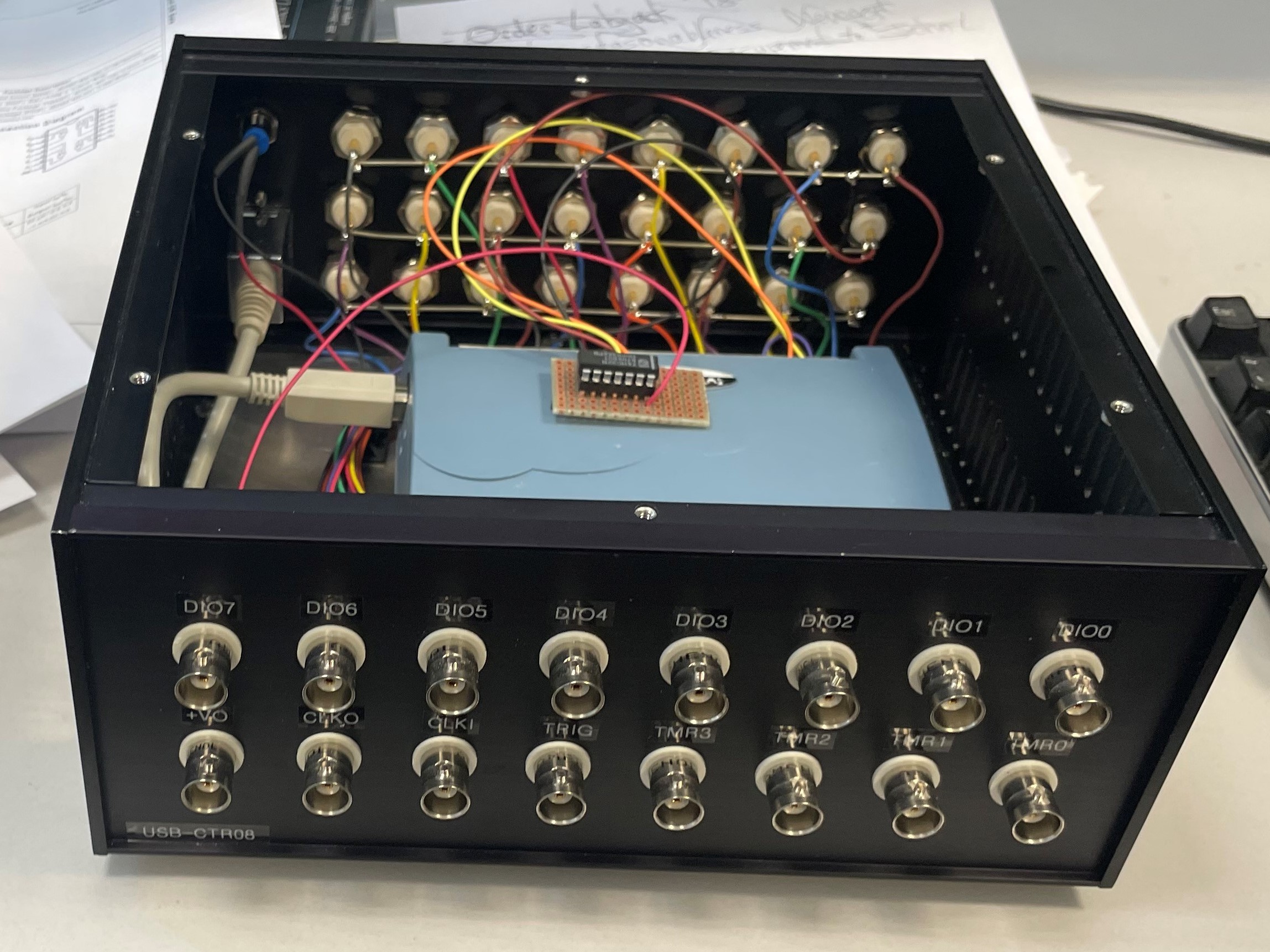
USB-CTR08 box showing 74HC32N for external gate
The photo below shows a box with the USB-CTR08 on the left, the USB-3114 in the middle, and the USB-1808X on the right. This box contains most of the analog input, analog output, digital I/O, and counter/timer functions required to run an experimental station at the APS.
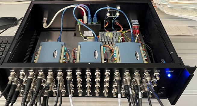
Box with the USB-CTR08, USB-3114, and USB-1808X
medm screens
The following is the main medm screen for controlling the USB-CTR04/08.
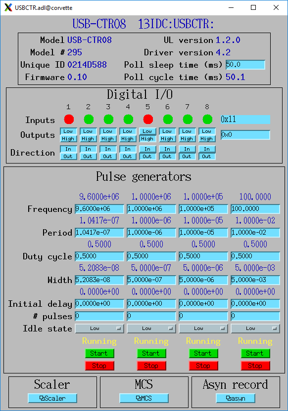
USBCTR.adl
The following is the medm screen for the EPICS scaler record using the USB-CTR04/08.
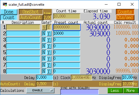
scaler_full.adl
The following is the medm screen for controlling the MCS mode of the USB-CTR04/08.
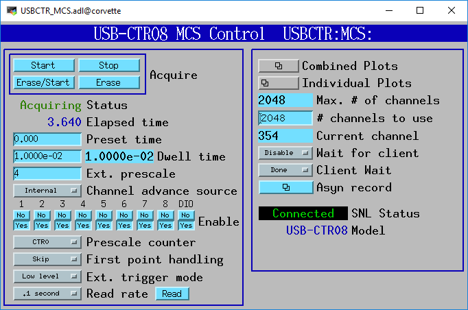
USBCTR_MCS.adl
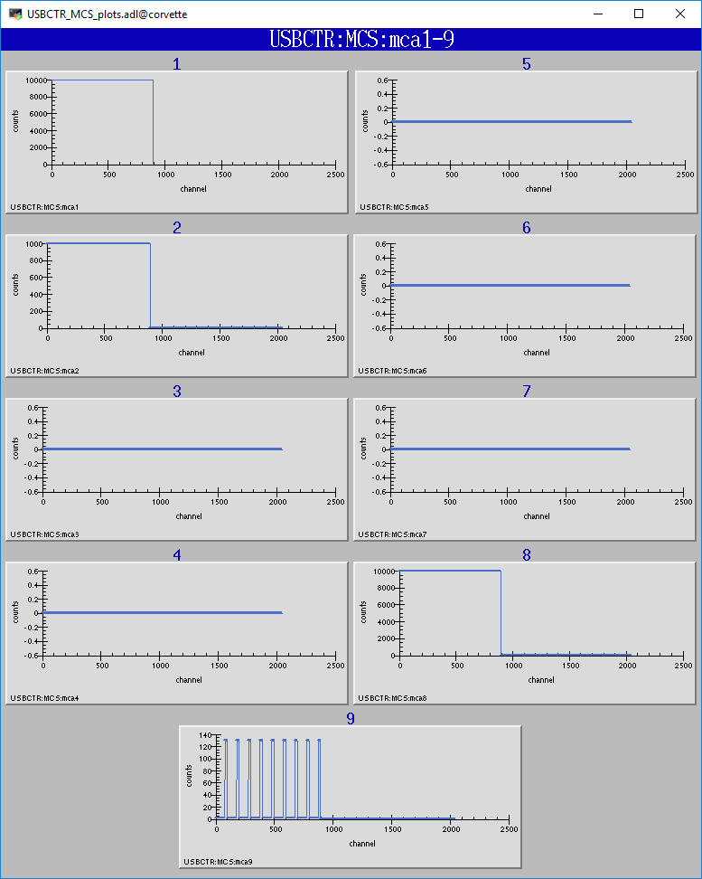
USBCTR_MCS_plots.adl
Performance measurements
The binary input bits are polled at 100 Hz, and the input records have SCAN=I/O Intr. There is thus a worse-case latency of 0.01 seconds in detecting a transition on these bits.
If the scaler record is run under the following conditions:
Counter 0 Output connected to the Gate Input of Counters 1-7
Pulse generator 0 frequency=32 MHz, connected to Counter 0 input
Pulse generator 1 frequency=32 MHz, connected to Counter 1 input
Pulse generator 2 frequency=32 MHz, connected to Counter 2 input
Pulse generator 3 frequency=32 MHz, connected to Counter 3 input
Scaler record .FREQ field = 3.2e7
Scaler record preset time = 1.0 second
Only scaler channel 1 is preset (.G1=Y, .G2-.G8=N)
After each count cycle .S1=32000000 counts exactly, .S2-.S4=32000000 += 1 count. There is thus no cross-talk with all channels running at 32 MHz, and the gate signals are working as designed.
If Pulse Generator 2 is changed to 3.2 MHz, .PR2 is set to 1600000, and .G2 is set to Y, then the scaler is stopped by channel 2 in the software polling routine. In this case it counts for exactly 0.50 seconds. However, if .PR2 is increased to 1600001 then it counts for 0.51 seconds. This corresponds to the worst case error due to the 100 Hz rate at which the scaler values are read. Note that all counters are active for exactly 0.51 seconds, so the counts all accurately reflect this count time. The count time is just slightly longer than requested due to the finite polling interval.
In MCS mode the measured minimum dwell time in both internal and external channel advance mode agrees with the datasheet, i.e. 250 ns * number of active counters. I was not able to measure any dead time between time bins in MCS mode. When sending exactly 8000000 pulses at 8 MHz to channel 0 with a 1 ms internal dwell time the total number of counts in the MCA record was 8000000. This means that no pulses were lost during the 1000 channel advances that happened during this time.
Restrictions
The EPICS driver only uses the Totalize mode of the counters. With the scaler record it does a one-shot totalize, while in the MCS mode it totalizes into time-bins. The USB-CTR08 is also capable of running in 3 other modes.
In Period mode it measures the time between the rising or falling edges of successive input pulses.
In Pulse Width measurement mode it measures the time between the rising and falling edges of a each pulse.
In Timing Mode it measures the time between an event on the counter input and another event on the counter gate.
None of these modes are currently supported by the EPICS driver, but they could be added in a future release.
In Totalize mode each counter has many options in how it works: count up/down, gate clears counter, gate controls counter direction, preset counts where the output signal goes high/low, polarity of the output, etc. These options are not currently exposed in the EPICS driver.
The EPICS driver only works in 32-bit counter depth mode. The USB-CTR08 can count with a 64-bit counter depth. asyn does not currently have support for 64-bit integer data types, so this cannot be supported.
To work with the scaler record the counter 0 output must be wired to the gate inputs of counters 1-7 as discussed above.